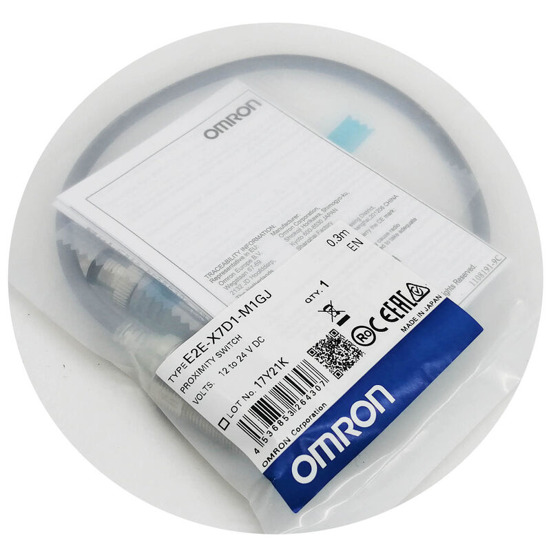
Omron E2E-X7D1-M1GJ | M18 Shielded 7mm Inductive Proximity Sensor — Panel Mount / M12 A-Coded / DC 2-Wire NO / IP67
Panel Mount Configuration — Sensing Through a Panel
The MJ suffix on the E2E-X7D1-M1GJ identifies the panel mount form factor with M12 connector. The sensor passes through a panel cutout from the rear, securing with a lock nut against the panel face, with the sensing window facing outward through the panel front. This is the opposite orientation from a machine-mount sensor that threads into a bracket with its sensing face aimed at passing targets.
The sensing performance is identical to the standard E2E-X7D1 M18 series — 7mm range, 500Hz switching frequency, IP67 oil-proof protection, dual LED indicators — with the form factor adapted for panel installation in quality inspection equipment, compact automation modules, and portable or tabletop equipment where the sensing point is at the device face.
The M12 connector mounts at the rear of the panel, keeping wiring clear of the sensing face. In maintenance-intensive environments, M12 connector standardisation means sensor replacement does not disturb the fixed cable run — disconnect the M12, install the new sensor, reconnect.
Key Specifications
| Parameter | Value |
|---|
| Sensing Distance | 7 mm |
| Setting Distance | 0–5.6 mm |
| Supply | 12–24V DC |
| Output | DC 2-wire NO |
| Switching Capacity | 3–100 mA |
| Leakage | 0.8 mA max |
| Frequency | 500 Hz |
| Connector | M12 A-coded |
| IP | IP67 |
7mm Shielded at M18 — The Right Specification
Shielded construction focuses the magnetic field forward, enabling flush installation in metal brackets without sensing distance penalty — the 7mm range applies with the sensor face flush with the bracket surface. M18 shielded at 7mm is the established specification for applications needing 5–7mm sensing clearance with flush mounting. The shielding suppresses the lateral fringing field that causes false detection when an unshielded sensor is installed flush in metal.
DC 2-Wire Circuit — Three mA Minimum, 0.8 mA Leakage
The 2-wire circuit connects in series with the load. At no-target condition: 0.8mA leakage through the load — below the ON threshold of standard 24V PLC inputs (typically 5–7mA minimum). At target-detected condition: current flows through the output stage and load from the supply.
For PLC inputs drawing 5–20mA at 24V, the 3mA minimum load current ensures the sensor output stage conducts correctly when the PLC input is connected as the load. Install with a parallel resistor if the load impedance is high enough that current draw falls below 3mA.
The 5.6mm setting distance — 80% of the 7mm nominal — is the reliable working zone. Set the physical gap at 3.5–4.5mm for comfortable margin against thermal expansion, vibration, and panel alignment variation.
FAQ
Q1: What M12 cable mates with the MJ connector?
Any M12 A-coded female cable connector — the dominant field connector standard in factory automation globally. A-coding distinguishes it from M12 B-coded (PROFIBUS), D-coded (Ethernet), and X-coded connectors. For the 2-wire DC connection, use Pins 1 (brown, +V) and 3 (blue, 0V/output) of a standard 4-pin M12 A-coded cable assembly. Pins 2 and 4 are unused in the 2-wire configuration.
Q2: What working gap should be set during installation?
Set the physical gap between sensor face and nearest target approach at 3.5–4.5mm. This keeps the switching point comfortably within the 5.6mm setting distance across the full operating temperature span and supply voltage range. Confirm the green LED illuminates steadily at the intended gap — this verifies the gap is within the reliable setting zone.
Q3: Does the 7mm range apply to stainless steel targets?
Austenitic stainless steel (304/316 grade) has a correction factor of approximately 0.6–0.75×, producing an effective switching distance of approximately 4.2–5.25mm for this sensor. This is within the 5.6mm setting distance, so stainless steel detection is achievable if the installation gap is within the effective stainless range. Always verify the actual switching distance with the specific stainless grade and target geometry in the actual installation.
Q4: How do the dual LEDs assist during installation and operation?
Green LED: Steady green with no target present confirms no metallic surface is within 5.6mm of the sensing face — no accidental interference nearby. Steady green when target is at the intended gap confirms the gap is within the reliable setting distance.
Red LED: Illuminates when a target enters the sensing field. Flickering red during target approach indicates the gap is at or near the stable switching zone boundary and needs adjustment.
Q5: Does the panel mounting affect IP67 sealing?
The sensor body maintains IP67 sealing in any mounting orientation. The M12 connector achieves IP67 sealing when the cable connector is fully mated and locked. However, the panel bore itself is not an IP67-sealed interface between the panel front and rear environments. If environmental separation between panel sides is required — for example, washdown on the front side with clean conditions at the rear — additional sealing around the sensor body in the panel bore may be needed.


 Your message must be between 20-3,000 characters!