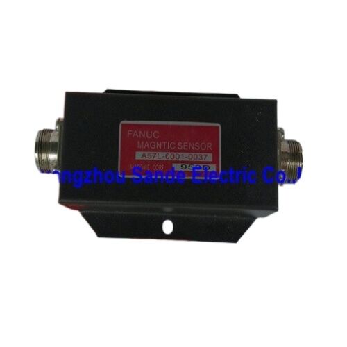
Fanuc A57L-0001-0037 | Spindle Orientation Magnetic Sensor — Type II, 12,000min⁻¹, DC 15V, 1ppr Two-Channel, 30×50mm
Overview
The Fanuc A57L-0001-0037 is a complete spindle orientation magnetic sensor set — the hardware that allows a Fanuc spindle to stop at a precisely defined angular position and hold it there.
Tool changes, workpiece loading, live tooling engagement, tapping operations, and any machining function that requires the spindle to present a fixed orientation rather than simply stop moving all depend on this module generating the position feedback that the CNC spindle controller needs to execute the orientation command.
The sensor operates at up to 12,000 min⁻¹, generating one output pulse per revolution on two independent channels.
Two channels — CH1 (MSA–MSB) and CH2 (LSA–LSB) — provide redundant position signals that the CNC uses to determine when the spindle has reached its target orientation angle.
The magnetic sensing principle means the sensor responds to the magnet embedded in the spindle's rotating assembly regardless of coolant, cutting fluid, or metal dust that would interfere with optical sensors in the same environment.
Unlike servo motor encoders that generate thousands of pulses per revolution for closed-loop velocity and position control, the A57L-0001-0037 generates exactly one pulse per revolution — a single reference mark event that identifies the orientation position.
The CNC drives the spindle through orientation at controlled speed, watches for the pulse, then commands deceleration and hold at the exact angle defined by the machine builder's orientation position parameter.
Key Specifications
| Parameter |
Value |
| Type |
Type II Magnetic Sensor |
| Maximum Speed |
12,000 min⁻¹ |
| Dimensions |
30 × 50 mm |
| Supply Voltage |
DC 15V ± 5% |
| Voltage Range |
0V to +18V |
| Current Consumption |
100 mA or less |
| CH1 Output |
1 pulse/rev (MSA–MSB) |
| CH2 Output |
1 pulse/rev (LSA–LSB) |
| Operating Temperature |
0°C to +50°C |
| Humidity |
30%–90% RH (non-condensing) |
| Sensor Head |
FSH-1378 |
| Application |
Spindle orientation, spindle module positioning |
Spindle Orientation — What This Sensor Actually Does
Spindle orientation is the function that drives a CNC machine's spindle from whatever speed and angle it was running at to a specific, repeatable angular position — typically measured in fractions of a degree from the orientation reference mark.
Every tool change on a machining centre requires the spindle to present the tool holder's key to the magazine arm at a defined angle; orientation is how that angle is found and held with enough force to prevent the tool holder from rotating during the engagement.
The A57L-0001-0037 creates the reference event — the "I'm here now" signal — at one specific angle per revolution.
Before orientation is commanded, the spindle is freewheeling or running at cutting speed and the sensor output is simply cycling once per revolution at whatever speed corresponds to spindle RPM. When the CNC commands orientation, the spindle drive decelerates and the controller begins looking for the next sensor pulse.
When the pulse arrives, the controller knows the spindle is at the reference angle and applies the position loop to drive it to and hold it at the target offset from that reference.
Type II designation in Fanuc's sensor nomenclature refers to the specific sensor signal format and connector interface used in spindle modules compatible with this module.
Type I and Type II sensors are not interchangeable — the signal conditioning circuits inside the spindle amplifier are matched to the sensor type specified for that amplifier/spindle combination.
Magnetic Sensing Principle and Coolant Resistance
Hall-effect magnetic sensors detect the presence of a magnetic field — the rotating magnet attached to the spindle creates a field pulse each time it passes the stationary sensor head (FSH-1378).
Because the detection is based on field strength rather than light transmission, the sensing path can be physically interrupted by coolant film, chips, mist, or oil contamination without affecting the output — as long as the gap between the rotating magnet and the sensor head remains within the specified range.
This coolant immunity is practically important: the spindle nose is exactly the area of the machine most exposed to cutting fluid, and orientation sensors mounted near the spindle must survive continuous wash from high-pressure coolant. Optical orientation sensors (phototransistors detecting a reflective mark on the spindle) require clean optical paths and window protection; the A57L-0001-0037's magnetic design is inherently indifferent to the fluid environment at the sensing point.
The installation requirement — keeping the cable side of the sensor head, amplifier, and connecting cables free from lubricant and coolant — applies to the cable assemblies and amplifier, not to the sensing face itself.
Cable and connector damage from sustained fluid exposure is the primary maintenance concern, not the sensor head's detection function.
Installation Considerations
The sensor head (FSH-1378) mounts on the stationary spindle housing; the magnet mounts on the rotating spindle body.
The gap between magnet and sensor face determines the signal amplitude. Fanuc specifies the correct gap distance in the spindle module maintenance manual — too wide a gap reduces signal amplitude below the amplifier's detection threshold; too small a gap risks physical contact between rotating magnet and stationary sensor at higher speeds or under vibration.
When the spindle incorporates a magnetic clutch for high/low gear switching, the magnet for the A57L-0001-0037 must be mounted on a non-magnetic material surface on the rotating assembly to prevent the clutch's magnetic field from interfering with the sensor signal.
In belt-connected or gear-connected spindle configurations where the motor and spindle are not rigidly coupled, the sensor mounts on the spindle side of the drive to detect spindle position directly — not motor position, which would introduce errors equivalent to the mechanical compliance of the drive transmission.
The 30 × 50mm sensor head dimensions determine the available mounting space and must be accommodated in the spindle housing design.
Clearance for the cable exit and the sensor amplifier's mounting location should be verified against the machine's available space before installation.
FAQ
Q1: Does the A57L-0001-0037 control spindle orientation by itself, or does it need additional components?
The A57L-0001-0037 is the sensor set — it detects the orientation reference position and signals it to the CNC, but it does not control the spindle independently.
The complete orientation function requires the sensor, the spindle amplifier (which has the orientation control logic), and the CNC controller that issues the orientation command and monitors completion. The sensor provides the "one pulse per revolution" reference; the amplifier and CNC jointly execute the decelerate-locate-hold sequence.
Q2: What is the difference between CH1 (MSA–MSB) and CH2 (LSA–LSB), and are both channels always used?
Both channels produce one pulse per revolution at the same angular position.
They are electrically independent outputs from the same sensor, allowing the CNC or amplifier to use one as a primary signal and the other as a confirmation channel, or to route them to different inputs for different functions (such as one for orientation and one for zero-speed detection).
Whether both channels are used depends on the spindle amplifier model and CNC configuration. Some amplifiers use only CH1; others use both. Consult the spindle amplifier installation manual for the specific connection scheme required.
Q3: The sensor is rated to 12,000 min⁻¹ — does the maximum speed limit when orientation can be commanded?
The 12,000 min⁻¹ rating is the speed at which the sensor reliably generates the orientation pulse without missing events. The orientation sequence itself is normally commanded with the spindle either stopped or decelerating from cutting speed — not at full speed.
The CNC's orientation function typically decelerates the spindle to an approach speed before seeking the reference pulse and then to zero for final position hold. The sensor's 12,000 min⁻¹ limit ensures it operates correctly throughout the deceleration phase even when the machine's maximum spindle speed equals this value.
Q4: How is the gap between the sensor head and magnet correctly set?
The gap specification is given in the Fanuc spindle module maintenance documentation for the specific machine model and spindle configuration.
Typical gaps for Hall-effect sensor applications of this type are in the 0.5–2.0mm range, but the exact requirement for A57L-0001-0037 must be verified from Fanuc documentation for the applicable spindle.
The amplifier's signal LED or output voltage diagnostic is used to confirm that the signal amplitude is within the acceptable window at the set gap, before locking the sensor in its final position.
Q5: What symptoms indicate the A57L-0001-0037 needs replacement?
The most direct indicator is an orientation failure alarm on the CNC — the spindle spins through the orientation sequence but the controller never receives the reference pulse and times out.
Other symptoms include intermittent orientation failures (suggesting a marginal signal due to gap drift, cable damage, or contamination on the cable connectors), orientation stopping at the wrong angle every other cycle (suggesting the signal is noisy enough to trigger spuriously), or complete loss of orientation function.
Before replacing the sensor module, check the cable routing and connectors for coolant ingress, and verify the gap is within specification using Fanuc's diagnostic outputs.


 Your message must be between 20-3,000 characters!