Omron E2E-X3D1-N | Inductive Proximity Sensor — M12 Shielded, 3mm NO, DC 2-Wire, 10–30VDC, 1kHz, Dual LED, IP67 Oil-Proof, 2m Pre-Wired Cable
Overview
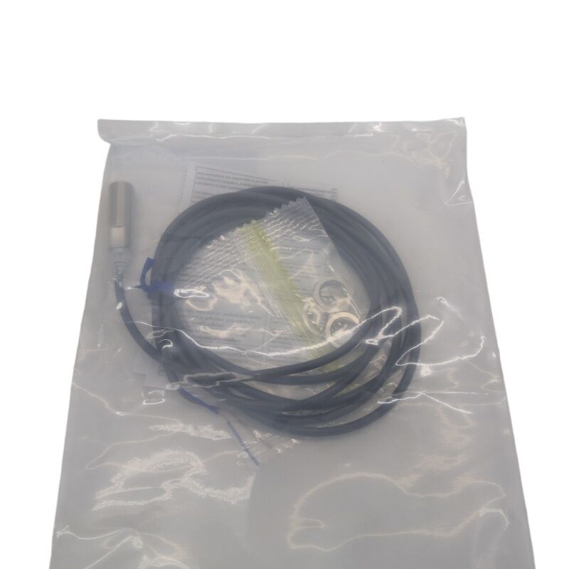
The Omron E2E-X3D1-N is an M12 shielded inductive proximity sensor with a 3mm sensing distance and DC 2-wire normally open output, pre-wired with a 2-metre oil-resistant PVC cable.
It is the cable-type variant of the E2E-X3D1 sensor platform — "N" identifies the pre-wired construction without a field connector — making it the direct-wire choice for installations where connecting a cable to a terminal strip is preferred over a quick-disconnect M12 connector system.
Within Omron's E2E series, the X3D1-N at M12 body size occupies a practical middle ground. The M12 thread and 3mm sensing distance represent the most widely deployed size-to-range combination in general industrial machine tool and automation applications.
The step up from M8 (2mm sensing) to M12 (3mm sensing) adds a millimetre of detection clearance — reducing the sensitivity to mounting misalignment, target surface variation, and structural thermal expansion that can shift the actual sensing gap away from its set value during production.
The pre-wired 2-metre cable suits machine configurations where the sensor is located within a few metres of the control panel or terminal box.
No connector pin assignment table is needed, no field connector to source or assemble — the sensor arrives with its wire ends bare and ready for terminal connection.
For higher-vibration installations or applications requiring sensor replacement without disconnecting fixed cable runs, the M1G connector variant provides the same electrical specification with a field-disconnectable M12 interface.
Key Specifications
| Parameter |
Value |
| Sensing Distance |
3 mm (±10%) |
| Setting Distance |
0–2.4 mm |
| Housing |
M12 × 1mm, shielded, nickel-plated brass |
| Output |
DC 2-wire, NO, polarised |
| Supply Voltage |
12–24V DC |
| Operating Range |
10–30V DC |
| Switching Capacity |
3–100 mA |
| Leakage Current |
0.8 mA max |
| Response Frequency |
1 kHz |
| Cable |
2m oil-resistant PVC |
| IP Rating |
IP67 + oil-proof |
| Indicators |
Red LED (output) + Green LED (range) |
| Standards |
EN60947-1, EN60947-5-2, CE |
Dual LED Indicators — Commissioning Built Into the Housing
The E2E-X3D1-N carries two LED indicators that serve separate, complementary functions. The red LED mirrors the output state — on when the output is conducting, off when open — providing continuous operational confirmation without a diagnostic tool.
The green LED indicates whether the target is within the 0–2.4mm setting range, showing that the sensor is operating in its reliable detection zone rather than at the fringe of its sensing capability.
During installation, the green LED is the primary commissioning tool. With the machine assembled, target in position, and power applied, a steady green LED confirms the current gap is within the reliable setting distance.
If the green indicator fails to light or flickers as the target moves through its travel, the gap exceeds the setting distance and the mounting position needs adjustment.
This eliminates trial-and-error gap setting and reduces the time between first power-up and confirmed reliable operation to a visual check.
DC 2-Wire NO — Simplicity With Defined Constraints
The DC 2-wire circuit places the sensor in series with the load between positive supply and common. When no target is present, the output is open with 0.8 mA leakage.
When a target enters the 3mm field, the output conducts and current flows through the load.
Two conductors — positive and load — carry both supply and signal function, eliminating the dedicated supply wire of 3-wire sensor designs.
The practical constraints are minimal: load current must be at least 3 mA for reliable switching (met by all standard PLC digital inputs), and the 0.8 mA off-state leakage must not reach the input's ON threshold (standard 24V PLC inputs switch at 5 mA or more, leaving the 0.8 mA leakage well clear).
For any load with unusual current characteristics, verify both parameters before installation.
The sensor's surge suppressor and short-circuit protection absorb installation errors and inductive load transients that would otherwise damage the output stage.
Shielded Flush Mounting — Field Versatility
Internal shielding focuses the electromagnetic sensing field axially, preventing the lateral field that would be absorbed by surrounding metal in a metal bracket installation.
The E2E-X3D1-N threads into M12 × 1mm holes, mounts flush or recessed into metal, and secures with standard M12 lock nuts.
For installations requiring the sensor face to be set back from the metal surface face, the setting distance range (0–2.4mm) provides the adjustment margin without changing the mechanical mounting configuration.
FAQ
Q1: What is the connection interface of the E2E-X3D1-N — how does the cable wire into a control panel?
The E2E-X3D1-N ships with 2m of oil-resistant PVC cable terminated with bare wire ends. Two conductors are provided: brown wire (supply positive — connect to +24V DC) and blue wire (load/output — connect in series with load to supply common).
Terminal screws in the control panel or machine junction box receive the bare ends directly. No connector adapter or tool is required beyond a screwdriver.
Q2: How does the 1kHz response frequency affect the choice of this sensor for counting applications?
At 1kHz, the sensor completes 1,000 full ON/OFF detection cycles per second. For reliable counting, each target must remain within the sensing field for at least one full cycle — meaning very fast-moving small targets may be missed.
A practical limit: targets passing at 1 m/s past a 3mm sensing zone transit in approximately 3ms, covering 4.5 switching cycles at 1kHz — reliable. At 10 m/s, transit time drops to 0.3ms, less than one cycle.
For applications with fast-moving target arrays, calculate the expected transit time against the 1kHz period to confirm reliable counting.
Q3: The standard sensing object is iron 12 × 12 × 1mm — what reduction applies to aluminium targets?
Aluminium has a correction factor of approximately 0.3–0.4× for shielded E2E M12 sensors. For the E2E-X3D1-N with a 3mm iron rating, aluminium targets of the same size produce an effective switching distance of approximately 0.9–1.2mm.
Smaller aluminium targets reduce further. When detecting aluminium in machine applications, measure the actual switching point with the specific part and validate it against the installation gap before fixing the sensor position.
Q4: Can the E2E-X3D1-N be replaced with the M1G connector variant without changing the PLC wiring?
The sensing specifications, output circuit, and supply voltage are identical between the E2E-X3D1-N (cable) and E2E-X3D1-M1G (M12 connector).
Replacing with the connector variant requires sourcing a compatible M12 field cable assembly and routing it to the control panel terminal — the PLC terminal strip wiring can remain unchanged, with only the field cable added between the terminal and the sensor connector.
The connector pin arrangement (brown = pin 1 = +V, blue = pin 4 = 0V) must match the cable assembly's wiring.
Q5: Does the E2E-X3D1-N require any adjustment after installation?
No adjustment is required. The sensor is factory-calibrated for 3mm nominal sensing distance.
After mounting at a gap within the 0–2.4mm setting range and connecting the wiring, verify operation by confirming the red LED illuminates when the target is in range and the green LED is steady (indicating the gap is within the reliable setting distance).
If the green LED is off or unstable, reduce the gap until it illuminates steadily. No potentiometer or programming is needed.


 Your message must be between 20-3,000 characters!