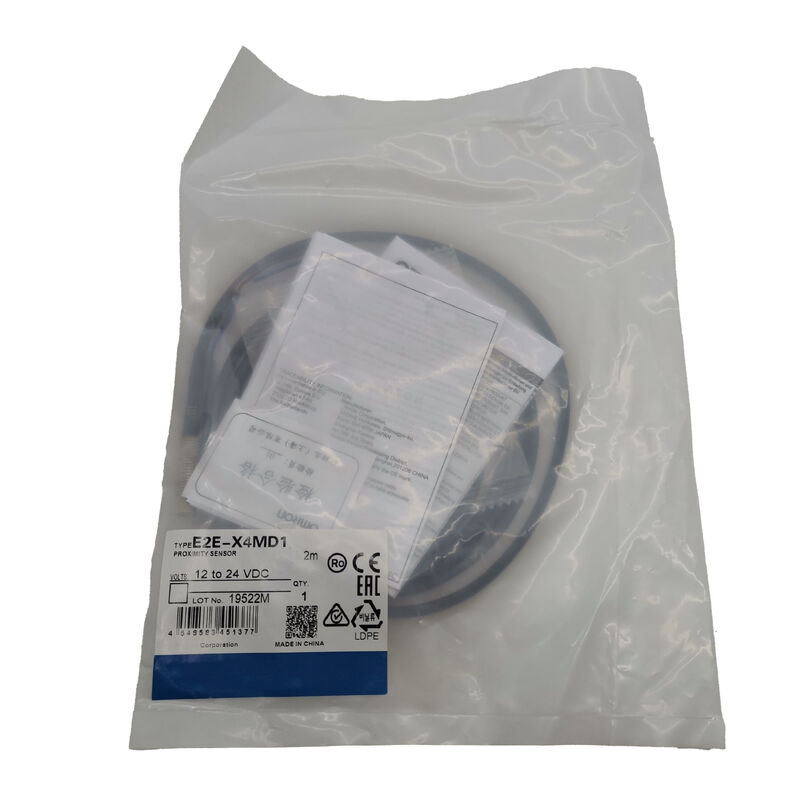
Omron E2E-X4MD1 | Inductive Proximity Sensor — M8 Unshielded, 4mm NO, DC 2-Wire, 10–30VDC, 1kHz, Dual LED, Stainless Steel, IP67, 2m Cable
Overview
The Omron E2E-X4MD1 is an M8 unshielded inductive proximity sensor delivering a 4mm sensing distance with DC 2-wire normally open output.
In Omron's E2E sensor matrix, the "MD" designation identifies the unshielded (non-flush) M8 medium-range variant — the model where the M8 body's sensing capability is maximised by eliminating the internal shielding ring, extending the electromagnetic field laterally as well as forward, and achieving 4mm detection range from a housing where shielded construction yields only 2mm.
The trade-off is installation constraint: without internal shielding, the sensor's laterally extending field is absorbed by surrounding metal if the sensor face is flush with a metal bracket.
Unshielded installation requires a metal-free zone around the sensing face — the sensor must protrude from its mounting hole, with the surrounding metal surface sitting behind the active sensor tip at a specified standoff distance.
This is a manageable installation requirement in most applications; when a longer sensing range within the compact M8 body is more important than the ability to flush-mount in metal, the E2E-X4MD1 is the correct selection.
The stainless steel (SUS303) housing and oil-resistant PBT sensing surface set the E2E-X4MD1 apart from standard proximity sensors that use brass or zinc housings — materials that are more vulnerable to the alkaline coolants and chlorinated cutting fluids present in machine tool environments.
Both housing and sensing surface maintain their dimensional accuracy and chemical integrity in sustained fluid exposure.
Key Specifications
| Parameter |
Value |
| Sensing Distance |
4 mm (±10%) |
| Setting Distance |
0–3.2 mm |
| Differential Distance |
15% max of Sn |
| Standard Target |
Iron 20 × 20 × 1 mm |
| Housing |
M8 × 1mm, unshielded, SUS303 stainless |
| Output |
DC 2-wire, NO, polarised |
| Supply Voltage |
12–24V DC |
| Operating Range |
10–30V DC |
| Switching Capacity |
3–100 mA |
| Residual Voltage |
3V max |
| Leakage Current |
0.8 mA max |
| Response Frequency |
1 kHz |
| Cable |
2m oil-resistant PVC |
| IP Rating |
IP67 |
| Indicators |
Red + Green LED |
Unshielded Construction — 4mm From an M8 Body
The relationship between shielding and sensing range is direct in inductive sensor design: internal shielding confines the oscillating electromagnetic field to a forward-projecting cone, protecting flush-mounted installations from metal absorption but inherently reducing field intensity and therefore sensing range.
Removing the shield allows the field to expand in all directions from the coil, producing a larger sensing volume and longer range at the cost of lateral field extension.
At M8 body size, the shielded E2E achieves 2mm; the unshielded E2E-X4MD1 achieves 4mm from the same body diameter.
That 2mm gain — 100% improvement in sensing distance — is significant in applications where the target approach path is constrained by machine geometry and cannot come closer than 4mm to the sensor face, or where the target is smaller than the standard test plate and the extra sensing distance partially compensates for the reduced target area.
The 15% maximum differential distance (versus 10% for shielded models) reflects the inherently softer switching characteristic of unshielded sensors.
The switching point varies over a slightly larger zone as the target approaches and retreats from different directions — not a concern for position detection in controlled travel paths, but worth noting for high-precision position repeatability requirements.
Dual LED + Diagnostic Output Delay
Like other E2E models with the dual-indicator design, the E2E-X4MD1 carries both a red output LED and a green setting-range LED. The red LED confirms each detection event instantly; the green LED confirms the sensor is operating within its reliable 0–3.2mm setting distance, providing a continuous installation health check during production.
The diagnostic output delay of 0.3 to 1 second is a specific feature of this model: in self-diagnostic configurations, the sensor monitors its own operating condition and generates a delayed output signal when a diagnostic condition (such as operation near the limit of the sensing range or a detected anomaly) is identified.
In standard position sensing applications, this delay is part of the sensor's diagnostic function rather than the primary switching output — verify the specific wiring configuration against the sensor's output circuit documentation when integrating diagnostic output monitoring into the control system.
Residual Voltage and Load Compatibility
The residual voltage of 3V max applies to the output circuit when the sensor is conducting — with 2m cable at rated load. In a 24V DC supply system, 3V residual means the load sees approximately 21V when the sensor output is ON. For standard PLC input cards with a minimum ON voltage of 11V, this is well within specification.
For load devices with higher minimum ON voltages (some older relay coils or pilot lights designed for full 24V operation), verify that 21V at the load terminal is sufficient to activate the device reliably under all conditions including low-end supply voltage tolerance.
FAQ
Q1: What is the required "metal-free zone" for the E2E-X4MD1 unshielded installation?
Omron specifies the mounting metal-free zone in the E2E series installation documentation based on sensor body diameter. For M8 unshielded sensors, the metal bracket's bore should be chamfered or countersunk so that no metallic material exists within approximately 1× the sensor's body diameter (8mm) of the sensing face perimeter.
The sensor tip must protrude from the mounting hole by a specified distance. These dimensions are provided in Omron's installation diagrams and vary slightly by body size and sensing distance — always verify against the E2E catalogue data for M8 unshielded models.
Q2: The standard sensing object is 20 × 20 × 1mm iron — larger than the M12 sensor's 12 × 12mm target. Why?
The larger standard target area compensates for the wider, less focused sensing field of an unshielded sensor. Unshielded inductive sensors project a broader electromagnetic field than shielded types, requiring a larger target area to return sufficient flux to the receiver for reliable switching.
The 20 × 20mm test plate ensures the sensing characterisation reflects field coverage across the full unshielded field geometry. In applications where the actual target is smaller than 20 × 20mm, measure the actual switching distance with the real target — effective range may be shorter depending on target area.
Q3: Can the E2E-X4MD1 detect non-ferrous metals like aluminium or copper?
Yes, but at shorter effective sensing distances. Non-ferrous metals have correction factors relative to iron: aluminium approximately 0.3–0.4×, brass approximately 0.4–0.5×, copper approximately 0.3×. At 4mm iron sensing distance, aluminium targets produce an effective range of approximately 1.2–1.6mm — still detectable but requiring a much closer installation gap. Always verify with the specific metal alloy, thickness, and target dimensions, as alloy composition significantly affects the correction factor.
Q4: The operating temperature is −25°C to +70°C for the sensor, −40°C to +85°C for storage. Is there a break-in period after cold storage?
No specific break-in procedure is needed, but after storage at very low temperatures (below −25°C) the sensor should be allowed to equilibrate to operating temperature before use. Powering an inductive sensor when its internal components are below the rated operating minimum risks condensation forming inside the housing if ambient moisture is present, and the electronic components may not perform within specification until within the operating temperature range.
Standard industrial practice is to bring cold-stored sensors to operating temperature in a clean, dry environment before installation.
Q5: What is the difference between the E2E-X4MD1 and E2E-X4MD2 variants?
The D1 suffix indicates normally open (NO) output — output conducts when target is detected.
The D2 suffix is the normally closed (NC) variant — output conducts when no target is present and opens when target is detected. All other specifications (sensing distance, housing, frequency, supply, cable) are identical.
Choose D1 for standard presence-detection circuits where target detection activates the load; choose D2 for fail-safe circuits or reverse-logic applications where idle-state output is required.

 Your message must be between 20-3,000 characters!