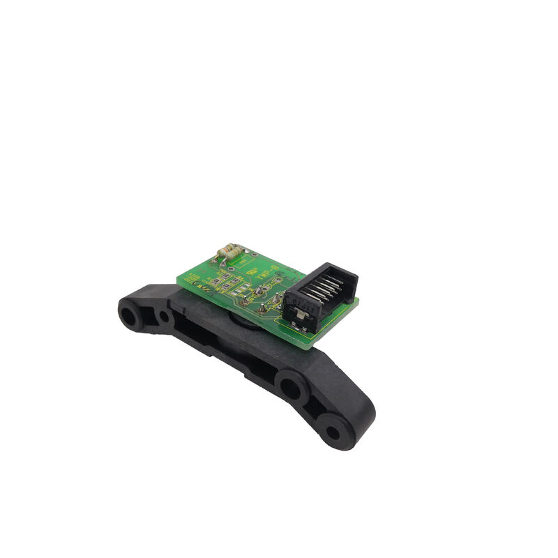
Fanuc A20B-9001-0780 | AC Spindle Motor Optical Sensor — 12-Pin Feedback Device, Speed and Position for CNC Spindle Control, Complete Sensor with PCB
Overview
The Fanuc A20B-9001-0780 is an optical pickup AC spindle motor sensor — the feedback device mounted on early-generation Fanuc AC spindle motors to provide the CNC and spindle amplifier with the speed and angular position signals necessary for closed-loop spindle control, including rigid tapping, spindle orientation, and Cs contour control.
Understanding this sensor's role requires a brief look at how Fanuc AC spindle motor control evolved.
In the early period of CNC AC spindle drives — spanning roughly the late 1970s through the 1990s — Fanuc developed its own AC spindle motor and drive systems as integrated packages.
The spindle motor was not a general-purpose induction motor running open-loop at variable frequency; it was a purpose-designed motor with a feedback sensor mounted on its shaft or body that allowed the CNC to know the exact spindle speed and position at all times.
This feedback was essential for functions that simple open-loop speed control cannot support: spindle orientation (stopping the spindle at a precise angular position for tool change), rigid tapping (synchronising Z-axis feed to spindle rotation for thread cutting without a floating tap holder), and Cs contour control (using the spindle as a CNC-controlled rotary axis for part turning on a machining centre).
The optical pickup design uses a slotted disk or reflective pattern rotating with the spindle motor shaft, read by a light source and photodetector assembly mounted in the sensor housing. As the disk rotates, the photodetector alternately sees the opaque and transparent regions, generating a pulse train whose frequency is proportional to rotational speed.
A reference mark on the disk generates a single pulse per revolution for absolute position within one rotation — the signal used by the CNC for spindle orientation and rigid tapping zero-crossing detection.
The 12-Pin Connector and Signal Assignment
The 12-pin connector on the sensor carries the complete signal set required by the Fanuc spindle amplifier: the pulse output signals (typically A, B quadrature channels plus a zero-reference Z channel), power supply lines (the sensor requires a low-voltage supply from the amplifier or a dedicated power source), and shielding connections.
The connector's 12-pin count accommodates these signal lines plus differential signal pairs — the complementary A/Ā, B/B̄, Z/Z̄ arrangement used in differential encoder outputs to provide common-mode noise rejection on cable runs in the electrically harsh environment around a spindle motor.
The differential signalling is particularly important for spindle sensors because the spindle motor generates substantial electromagnetic interference — the motor's own power leads, PWM-driven current waveforms, and the physical proximity of the drive electronics all contribute to noise in the sensor cable.
The sensor's optical design also inherently limits signal distortion from heat and vibration compared to magnetic pickup (variable reluctance) sensors that can be affected by ferromagnetic particles in cutting fluid and changes in air gap geometry as bearings wear.
Speed and Position Functions in CNC Spindle Control
The sensor's dual function — speed feedback and position feedback — enables three distinct operational modes in Fanuc CNC spindle control:
Speed control mode uses the pulse train from the sensor to close the speed feedback loop in the spindle amplifier.
The amplifier counts sensor pulses per unit time, computes actual spindle speed, compares it to the commanded speed from the CNC, and adjusts the motor drive current accordingly.
This closed-loop speed control maintains constant spindle speed under varying cutting load — when a heavy cut increases the load torque, the amplifier detects the speed drop immediately through the sensor feedback and compensates by increasing motor torque output.
Spindle orientation uses the zero-reference (marker) pulse to detect when the spindle reaches a specific angular position.
The CNC commands the spindle to decelerate and stop at the position where the orientation mark is detected, bringing the spindle to rest at a mechanically reproducible position for tool change, part handling, or workpiece measurement.
On machining centres, spindle orientation is an automatic operation triggered at each tool change cycle.
Rigid tapping synchronises the Z-axis lead screw motion to the spindle rotation so that every revolution of the spindle corresponds to exactly one thread pitch of Z-axis movement. The CNC reads the spindle sensor position feedback in real time and feeds it to the Z-axis servo interpolation, creating a synchronised thread cutting motion without mechanical floating tap holders.
The spindle sensor's position resolution determines the thread pitch accuracy achievable in rigid tapping.
Complete Sensor with PCB — What "Complete" Means
The A20B-9001-0780 is described and sold as the complete sensor assembly, which includes both the optical pickup housing (with LED light source and photodetector) and the PCB (printed circuit board) that conditions and amplifies the photodetector's raw signal into the differential pulse outputs that the 12-pin connector delivers.
In some sensor designs, the optical pickup element and the signal conditioning electronics are separate components — the pickup element generates a weak analogue photodiode current, and the PCB amplifies and converts this to a clean digital output suitable for transmission over the cable to the drive.
The PCB also typically contains the power supply regulation for the sensor's internal electronics. When the sensor assembly is described as "complete with PCB," it means the buyer receives a functional, ready-to-mount sensor that requires only connection to the motor's mounting provision and the 12-pin cable to the amplifier — no separate PCB is needed.
This distinction matters in the repair and spare parts market because some sensor components are sold as individual elements — the pickup body alone, or the PCB alone — for technicians performing component-level repairs.
The A20B-9001-0780 sold as complete sensor with PCB is the full assembly for replacement of the entire sensor rather than component-level service.
A20B-9001-0780 and A20B-9001-0800 — Common Reference Numbers
The A20B-9001-0780 and A20B-9001-0800 are closely related references that appear together in the AC spindle sensor category for early Fanuc spindle motors.
Both are optical pickup 12-pin feedback sensors used for the same spindle motor control functions, and the two numbers are frequently cross-referenced in the Fanuc spare parts and repair market.
The relationship between these part numbers typically reflects different production versions or assembly variants of the same sensor family — different PCB board revisions or optical element configurations — that are functionally compatible and are used interchangeably in service applications on the same motor types.
In practice, when a spindle sensor from this family fails and the machine is down, both the -0780 and -0800 references are evaluated for the specific motor series and connector configuration before a replacement is selected.
The motor's original Fanuc documentation, nameplate, or the CNC's motor parameter data provides the definitive sensor type for a specific machine.
FAQ
Q1: What symptoms indicate that the A20B-9001-0780 spindle sensor has failed?
Common failure presentations include: spindle speed instability at low RPM (the CNC loses reliable pulse counting at low speeds, causing hunting or erratic speed), spindle orientation failure (the CNC cannot find the orientation mark position, causing the tool change cycle to abort with a position alarm), rigid tapping errors (synchronisation between spindle and Z-axis breaks down, resulting in damaged threads or tapping alarm), and complete loss of spindle feedback (spindle drive alarm, typically a speed feedback error or encoder disconnect alarm on the Fanuc spindle amplifier display). Physical contamination of the optical disc or pickup element — from cutting fluid ingress through a worn shaft seal — is one of the most common failure mechanisms.
Q2: Can the A20B-9001-0780 sensor be cleaned and refurbished, or does failure require complete replacement?
In many cases, spindle sensors fail due to contamination rather than electronic component failure.
If cutting fluid, oil, or metallic particles have entered the sensor housing and contaminated the optical disc or pickup element, careful cleaning may restore function — provided the optical components themselves are not scratched or permanently damaged.
Service specialists who work on Fanuc spindle motors routinely clean and test sensors before condemning them.
If the PCB has failed due to moisture ingress or component aging, repair at the component level is also possible for technicians with appropriate electronics skills.
Complete sensor replacement (with a new or tested-good unit like the A20B-9001-0780) is the fastest path to returning the machine to production when on-site repair capability is not available.
Q3: The sensor is described as being for "early generation" AC spindle motors. What Fanuc CNC generations use this sensor?
This sensor type is associated with Fanuc's early AC spindle motor series — the motors paired with Fanuc 0-Series, 10-Series, 15-Series, and 16-Series CNCs, spanning machine tool builds from approximately the mid-1980s through the late 1990s.
Fanuc's later spindle motor generations — the Alpha series and then the Alpha i / Beta i series — use different sensor designs (the Mi sensor / A860-series encoder family) with different connectors and signal protocols.
The A20B-9001-0780 is specifically for the older motor generation and is not interchangeable with the sensors used on newer Fanuc Alpha or Alpha i spindle motors.
Q4: Is the sensor mounted on the spindle motor shaft, and does it require calibration or adjustment after replacement?
The optical pickup sensor is typically mounted at the rear of the spindle motor housing, sensing a slotted disc or target wheel that rotates with the motor shaft.
The mounting position is fixed by the motor's sensor bracket — the sensor aligns with the disc within the mechanical tolerances of the mounting.
In most cases, sensor replacement does not require calibration of the absolute position because the orientation reference position is defined by the disc's zero mark relative to the motor's mechanical zero, which is set during motor assembly.
However, after sensor replacement, the spindle orientation position should be verified on the actual machine and adjusted through the CNC's orientation offset parameter if the stopped position does not match the tool change position.
Q5: The sensor is available with or without cable. What cable is required if ordering without, and how critical is cable quality?
The 12-pin sensor cable carries differential pulse signals at relatively low voltages between the sensor and the spindle amplifier.
The cable must be shielded to protect the signals from electromagnetic interference in the vicinity of the spindle motor and drive.
Fanuc specifies shielded twisted-pair cable for encoder and sensor connections, with the shield grounded at the amplifier end. Using an inappropriate cable — unshielded, wrong impedance, or excessive length — can cause signal degradation that manifests as intermittent spindle alarms, erratic orientation, or rigid tapping errors without triggering a hard encoder fault.
When ordering without cable, using Fanuc-specified cable or a quality industrial shielded twisted-pair replacement of the correct conductor count and shielding specification is essential for reliable sensor operation.


 Your message must be between 20-3,000 characters!