Siemens 6ES7360-3AA01-0AA0 | SIMATIC S7-300 IM 360 — Central Rack Send Interface Module, K-Bus, Connects Up to 3 Expansion Racks, 350mA, 40×125×120mm, 225g
Overview
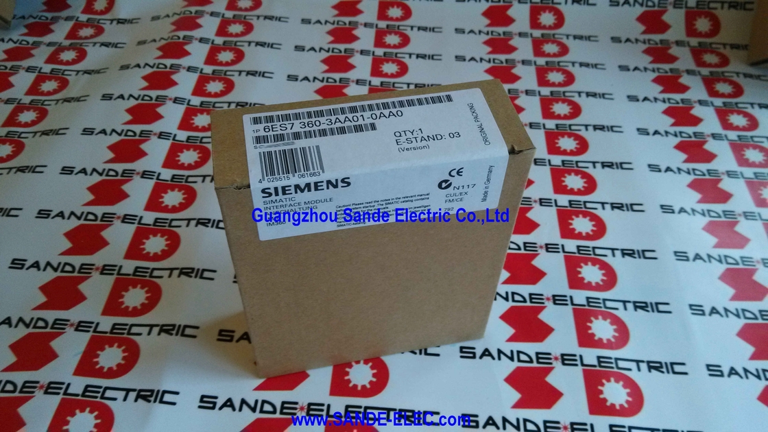
The Siemens 6ES7360-3AA01-0AA0 is the IM 360 — the central rack interface module that initiates a multi-rack S7-300 configuration.
Alone, it is the sending half of a pair — it takes the S7-300 backplane bus from the central rack's CPU and power supply and extends it outward, through the connecting cable, to up to three expansion racks.
Each expansion rack receives this extended bus through its own IM 361 receive module, and the combined result is an S7-300 system that spans multiple physical racks as a single, coherent PLC station from the CPU's perspective.
When a machine's automation task requires more I/O or more special function module capacity than one S7-300 rack can provide, the IM 360 is where that expansion begins.
It installs in the central rack's module slot — typically the slot immediately to the right of the CPU, with signal and function modules filling the remaining slots — and establishes the data link outward.
From the programmer's view in STEP 7, the modules in all connected expansion racks appear in the hardware configuration alongside the central rack's modules, assigned consecutive addresses in the same I/O address space. The physical separation across multiple racks is transparent to the user program.
Key Specifications
| Parameter |
Value |
| Role |
Central rack send (rack 0) |
| K-Bus Routing |
Yes (full C-bus pass-through) |
| Max. Expansion Racks |
3 |
| Backplane Current (rack 0) |
350mA |
| Max. Cable Length |
10m |
| Power Loss |
2W typical |
| Dimensions (W×H×D) |
40×125×120mm |
| Weight |
~225g |
| Compatible With |
IM 361 (6ES7361-3CA01-0AA0) |
| Number per CPU |
Max. 1 |
What "Send Module" Means in the S7-300 Architecture
In the S7-300 multi-rack interface pair, the IM 360 and IM 361 have defined roles that cannot be reversed or substituted for each other.
The IM 360 is specifically designed for the central rack — it originates the backplane bus extension and drives the connecting cable to the first expansion rack.
The IM 361 is designed for expansion racks — it receives the bus from the IM 360 (or from a previous IM 361 in a daisy chain) and provides it to the local expansion rack's modules.
Attempting to install an IM 360 in an expansion rack or an IM 361 in the central rack will not function — the hardware configuration in STEP 7 enforces the correct module placement, and physical connector differences prevent incorrect cable connections.
The IM 360 and IM 361 are complementary components of a system, not interchangeable.
The IM 360's backplane current output of 350mA is notably lower than the IM 361's 0.8A because the central rack already has its own power supply module (PS 307) providing the primary power — the IM 360's 350mA backplane contribution supplements the PS's output.
The expansion racks, which depend on the IM 361 as their primary backplane power source (combined with the PS 307 installed in each expansion rack), require the IM 361's higher 0.8A output.
The IM 360/361 System in Context
The IM 360 and its paired IM 361 units are the mechanism for the most capable S7-300 multi-rack configurations — those that need not just additional I/O, but the ability to distribute function modules, positioning controllers, and communication processors across multiple physical cabinets.
Consider a large printing press with four mechanical sections, each in its own cabinet several metres apart, where each section has its own motion control requirements (handled by FM 351 positioning modules), its own large I/O count (handled by signal modules), and its own safety interlock wiring.
The IM 360 in the main cabinet's S7-300 rack extends the backplane bus to three satellite cabinets, each with an IM 361 and its local modules.
The four FM 351 modules in the satellite cabinets communicate directly with the CPU via the K-Bus passing through the IM 360 and IM 361 chain — providing coordinated multi-axis motion control from a single S7-300 CPU without requiring separate communication protocols between the main cabinet and satellites.
This is the configuration that the IM 365 (with its simpler, no-K-Bus architecture) cannot support.
The IM 360/361 pair is the S7-300's answer to complex, distributed, multi-function machine control.
STEP 7 Configuration and Address Assignment
In STEP 7's hardware configuration (HW Config), the IM 360 appears as a component in rack 0 of the S7-300 station. The expansion racks (with their IM 361 modules) appear as racks 1, 2, and 3 in the same station configuration.
Modules installed in expansion racks are assigned I/O addresses in the same address space as the central rack's modules — there is no functional difference in how the CPU's user program accesses a digital input in rack 0 versus one in rack 3.
The I/O assignment and the rack configuration are defined in HW Config, and STEP 7 generates the correct address mapping automatically.
When downloading the hardware configuration, STEP 7 transmits the rack and slot assignments to the CPU, which then scans all racks and verifies that the physically installed modules match the configured ones.
If a rack is missing or a module is absent, the CPU generates diagnostics and marks the affected I/O as unavailable.
FAQ
Q1: Does the IM 360 require an external 24VDC power supply, like the IM 361 does?
No. The IM 360 is powered entirely from the S7-300 central rack's backplane — the same 5V DC supply that powers all other modules in the central rack. No external 24V DC supply is required for the IM 360 itself. In contrast, the IM 361 in each expansion rack requires its own 24V DC external supply.
This difference reflects the architectural distinction: the IM 360 in the central rack has the PS 307 power supply providing the central rack's power, while the IM 361 in expansion racks must provide its own backplane power source for the expansion rack's modules.
Q2: How many IM 360 modules can be installed in one S7-300 central rack?
Only one IM 360 per S7-300 CPU is permitted — the IM 360 connects one CPU to its expansion rack chain, and a single CPU supports at most one such chain. Multiple S7-300 stations (each with their own CPU) can each have their own IM 360, but within a single S7-300 station (one CPU and its associated racks), only one IM 360 is used.
This is consistent with the S7-300's architecture: one CPU manages all the modules in all connected racks as a single coherent station.
Q3: Can modules in the first expansion rack (rack 1) communicate with modules in the second expansion rack (rack 2), or only with the CPU?
All data exchange between modules in an S7-300 multi-rack station passes through the CPU's user program.
There is no direct module-to-module communication between expansion racks — a digital output in rack 2 cannot directly control an output in rack 3 without the CPU program reading the condition and writing the output.
This is consistent with standard PLC architecture: the CPU executes the program, reads inputs from all racks, processes logic, and writes outputs to all racks in each scan cycle. The IM 360/361 chain is a data transport infrastructure, not a peer-to-peer communication network.
Q4: What is the maximum total number of modules across all four racks (central + 3 expansion) in an IM 360/361 configuration?
Each S7-300 rack provides up to 8 module slots (positions 1–8 in the slot numbering, after the CPU/PS slots in rack 0). With one central rack and three expansion racks: 8 + 8 + 8 + 8 = 32 module slots maximum for signal, function, and communication modules.
The CPU itself (in rack 0) and one IM 360 (in rack 0) occupy two of rack 0's slot positions, reducing the practical maximum in rack 0.
Each expansion rack also uses one slot for the IM 361 receive module, reducing each expansion rack's available signal module slots to 7.
Q5: The product is in phase-out. Are there functional alternatives for new S7-300 designs?
For new machine designs requiring distributed I/O beyond a single S7-300 rack, Siemens recommends migrating to SIMATIC S7-1500 with ET 200SP or ET 200MP distributed I/O systems, connected via PROFINET.
The S7-1500 plus PROFINET distributed I/O approach achieves larger physical separation (up to 100m between PROFINET nodes), higher I/O density, and better diagnostics compared to the multi-rack IM 360/361 approach.
For existing S7-300 installations where the IM 360/361 must be maintained, spare modules are available from Siemens stock (while available) and the industrial surplus market.


 Your message must be between 20-3,000 characters!