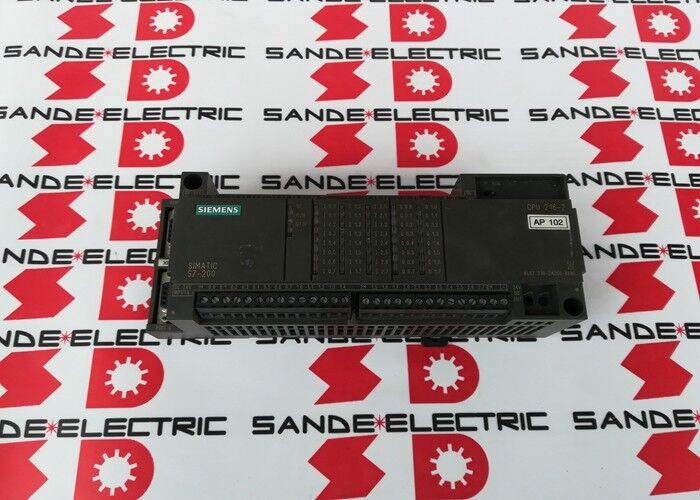
Siemens 6ES7216-2AD00-0XB0 | SIMATIC S7-200 CPU 216 — 4K Program / 24 DI DC + 16 DO DC / 2 RS-485 Ports
40 Built-In I/O Points, One DIN-Rail Unit
The CPU 216 is the largest standard CPU in the original S7-200 family — 24 digital inputs, 16 transistor digital outputs, power supply, processor, and two RS-485 communication ports in a single DIN-rail module. The 40 built-in I/O points cover a substantial range of machine control applications without requiring any expansion modules: all limit switches, proximity sensors, safety relay monitoring contacts, operator pushbuttons, motor contactor outputs, solenoid valve coils, and indicator lamps for a typical compact machine fit within these 40 points.
The transistor DC outputs switch in microseconds, have unlimited switching life (no contact wear), and can source or sink 24V DC loads at 0.5A per channel directly — contactors (50–200mA coil), solenoid valves (100–300mA), and LED indicators without external relay interposing hardware. For loads above 0.5A or requiring AC voltage, interposing relays provide the voltage and current conversion.
When the 40 built-in points are insufficient, the S7-200 EM expansion module series attaches to the right side of the CPU on the expansion bus, adding 8, 16, or 32 additional digital or analogue I/O points per module.
Two RS-485 Ports — PPI and Freeport
Port 0 (PPI mode): Siemens's native S7-200 serial protocol for programming access (STEP 7-Micro/WIN via PC/PPI cable or USB-PPI adapter), TD 200/OP operator panel connections, and PLC-to-PLC data sharing in multi-CPU networks. Up to 32 nodes per segment.
Port 1 (Freeport mode): When configured for Freeport, the port operates as a standard RS-485 serial interface under ladder program control. The program sends and receives bytes using XMT/RCV instructions, implementing whatever serial protocol the connected device requires — Modbus RTU to an energy meter, ASCII to a barcode scanner, RS-485 to a printer, scale, or remote display. This is the CPU 216's mechanism for integrating third-party serial devices without additional communication modules.
Two ports means PPI programming and HMI access on port 0 simultaneously with a Freeport field device connection on port 1.
Programme with STEP 7-Micro/WIN Only
The S7-200 is programmed exclusively with STEP 7-Micro/WIN. It is not compatible with STEP 7 Classic, TIA Portal, or any programming environment for the S7-300, S7-400, S7-1200, or S7-1500. Migrating from S7-200 to any current Siemens platform requires rewriting the programme in the new platform's engineering environment — STEP 7-Micro/WIN provides tools for checking and adapting programmes during migration, but direct transfer without modification is generally not possible between substantially different CPU types.
Key Specifications
| Parameter | Value |
|---|
| Program Memory | 4K words |
| Data Memory | 2.5K words |
| Digital Inputs | 24 × 24V DC |
| Digital Outputs | 16 × 24V DC, 0.5A transistor |
| Communication | 2 × RS-485 PPI/Freeport |
| Supply | 24V DC |
| Programming | STEP 7-Micro/WIN |
| Status | Discontinued |
FAQ
Q1: Can the 4K words of program memory be expanded?
No. Program memory in the CPU 216 is fixed at 4K words and cannot be expanded with external memory cards. A typical machine control programme with 20 input conditions, 10 timer/counter sequences, and 12 output actions occupies 500–1500 words — within the 4K limit. Complex programmes with extensive data manipulation, PID loops, and communication routines can approach the limit. If more memory is needed, upgrade to the CPU 226 (6ES7216-2AD23-0XB0), which offers 12K words of program memory.
Q2: Can the transistor outputs directly drive 24V DC relay coils?
Yes. Standard 24V DC relay coils draw 50–200mA — within the 0.5A per channel rating. Connect a freewheeling diode across inductive loads (relay coils, solenoid valve coils) to suppress the voltage spike when the output switches off. Many relay modules and solenoid valve manifolds include this diode internally; for bare coil loads, add external diodes.
Q3: Is the CPU 216 compatible with STEP 7 Classic or TIA Portal?
No. The S7-200 uses STEP 7-Micro/WIN exclusively — a completely separate engineering environment from STEP 7 Classic (S7-300/400) and TIA Portal (S7-1200/1500). Different instruction set, memory organisation, and communication protocol. Migrating to any S7-300, S7-1200, or S7-200 SMART requires rewriting the programme in the target platform's engineering tool.
Q4: What high-speed counter capability is built in?
High-speed counter inputs (on X0 and adjacent inputs) count pulse signals faster than the normal PLC scan cycle, independently in hardware. Maximum count rates: up to 2 kHz for incremental counting, up to 1 kHz for A/B phase quadrature counting for rotary encoders. The accumulated count is readable by the ladder programme via special registers (HC0, HC1, etc.).
Q5: Is the CPU 216 programme compatible with later S7-200 variants like the CPU 226?
Substantially compatible at the instruction level — the same ladder instructions run on all S7-200 variants. However, differences in memory addressing (different address ranges for expansion I/O), different numbers of built-in I/O points, and different special memory bit assignments require address adjustments when migrating to a different CPU type. STEP 7-Micro/WIN provides migration tools to check and adapt programmes during the transition.


 Your message must be between 20-3,000 characters!