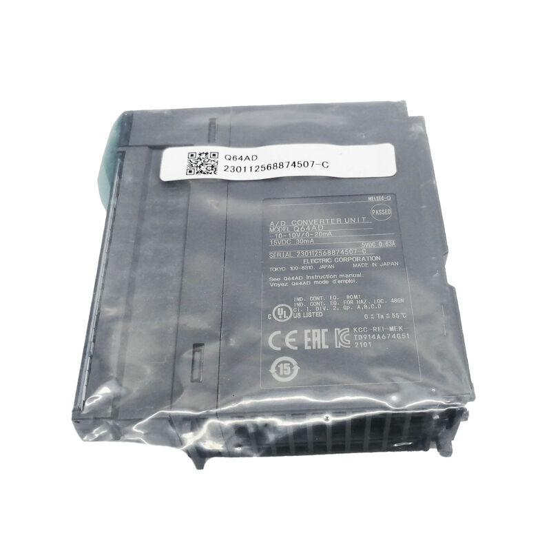
Mitsubishi Q64AD | MELSEC-Q 4-Channel 16-Bit Analog Input Module — ±10V + Current Input / 80µs / EEPROM / Photocoupler Isolation / 27.4mm
One Module, Any Industrial Analogue Signal
The Q64AD is the MELSEC-Q platform's general-purpose four-channel A/D converter — the module that covers all common industrial signal types from a single 27.4mm slot. Each channel is independently configured for its own input range: channel 1 on a ±10V pressure transmitter, channel 2 on a 4–20mA flow sensor, channel 3 on a 0–10V position feedback, channel 4 on a 1–5V temperature transmitter — all simultaneously active, all converting at 80µs per channel.
At 16-bit resolution, the Q64AD divides each input range into 65,536 counts. On the ±10V range, each count represents approximately 0.30mV. On the 4–20mA range, each count represents approximately 0.24µA. This resolution exceeds what most industrial transmitters can achieve in absolute accuracy, which means the module itself is not the limiting factor in measurement precision — the sensor and signal conditioning determine the practical accuracy ceiling.
Key Specifications
| Parameter |
Value |
| Channels |
4 |
| Resolution |
16-bit |
| Voltage Ranges |
±10V, 0–10V, 0–5V, 1–5V |
| Current Ranges |
0–20mA, 4–20mA |
| Conversion Speed |
80 µs / channel |
| Input Impedance (V) |
1 MΩ |
| Input Impedance (I) |
250 Ω |
| Max. Input (V) |
±15V |
| Max. Input (I) |
±30mA |
| EEPROM |
Yes |
| Isolation |
Photocoupler |
| Width |
27.4mm |
Averaging — Noise Suppression Without Slowing the Hardware
When sensor signal cables run near variable-frequency drives, motor starter panels, or other EMI sources, the converted digital value may show rapid variation around the true measurement. The Q64AD's digital averaging function addresses this without changing the 80µs hardware conversion speed.
Each channel independently selects time-based averaging (over a specified number of milliseconds) or count-based averaging (over a specified number of conversions). The module continues converting at 80µs internally; the averaged value is presented to the CPU as the reported measurement. A channel monitoring a fast-changing process variable can run without averaging, while an adjacent channel with a noisy signal uses heavy averaging — all from the same module, with no compromise to the unaveraged channels.
Application Scenarios
Process control PID loops: Pressure, flow, and temperature transmitters feeding 4–20mA signals to Q64AD channels. The CPU reads the converted values each scan and uses them as PV inputs to PID function blocks. EEPROM retention ensures the calibrated engineering unit relationship persists through the plant's maintenance shutdown cycles.
Multi-sensor machine monitoring: Condition monitoring of a production machine with force sensors (±10V bridge amplifier output), displacement transducers (0–10V), and temperature inputs (1–5V thermocouple transmitters) — all connected to one Q64AD without requiring separate specialised input modules for each signal type.
VFD speed feedback: Inverter analogue speed output (0–10V or 4–20mA) fed back to the Q64AD for closed-loop speed verification in web handling, winding, or conveyor applications.
FAQ
Q1: Does the Q64AD's 16 I/O point allocation reduce available discrete I/O?
Yes — intelligent function modules including the Q64AD occupy I/O points in the CPU's I/O map even though no physical discrete I/O terminals are involved. The 16-point allocation is for the module's data exchange signals. The actual converted values are read via FROM instructions accessing the module's buffer memory, not via the I/O image. This allocation must be included when calculating the system's total I/O point usage.
Q2: What protection does the Q64AD provide against input overvoltage?
The input circuits are protected against sustained inputs up to ±15V (voltage) and ±30mA (current). Signals within these limits do not damage the module. Brief transients from cable switching or ground faults may cause momentary conversion errors but should not damage the hardware if the exceedance is brief. Sustained connections of mains AC voltage to the input terminals would damage the input circuits; however, the photocoupler isolation protects the backplane and CPU from damage even if the analog input stage is compromised.
Q3: Can the Q64AD be calibrated in the field without factory service?
Yes. In offset/gain setting mode (activated via buffer memory write), the engineer applies a known reference signal to the input terminal, writes the corresponding target digital value, and the module calculates and stores the correction in EEPROM. This procedure corrects for sensor variation, cable drop, or installation-specific offset. The calibrated values persist through power cycles without any periodic maintenance action.
Q4: How many Q64AD modules can be installed in one Q-series system?
The limit is determined by total I/O point count and base unit slot availability, not by module type. A system supporting 64 slots across multiple base units connected via extension cables could theoretically hold 64 Q64AD modules — providing 256 analog input channels — subject to the system power budget, I/O point count, and the mix with other module types in the configuration.
Q5: Is averaging applied to all channels together or individually?
Individually. Each channel has its own independent averaging enable/disable and averaging parameter in the buffer memory. Channel 1 can run 50ms time-based averaging, channel 2 can run with no averaging, channel 3 can use 10-sample count-based averaging, and channel 4 can also run unaveraged — all simultaneously in the same module without any interaction between channels.


 Your message must be between 20-3,000 characters!