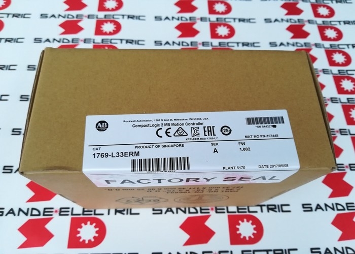
Allen-Bradley 1769-L33ERM | CompactLogix 5370 L3 EtherNet/IP Controller — 2MB, Dual Ethernet with DLR, 8-Axis CIP Motion, 32 Tasks, DIN/Panel Mount
Overview
The Allen-Bradley 1769-L33ERM is a CompactLogix 5370 L3 programmable automation controller with integrated motion over EtherNet/IP — the suffix "M" distinguishing it from the base 1769-L33ER by its built-in CIP (Common Industrial Protocol) motion capability that enables coordinated axis control without a separate motion controller module.
It sits in the middle of the CompactLogix 5370 L3 family, above the -L30ERM (which omits motion integration) and below the -L36ERM (which offers a 4MB memory step-up), making it the default selection for machine control applications that combine logic, I/O, and multi-axis servo motion in a single compact controller.
The controller's 2MB user memory accommodates substantial application programs: complex ladder logic routines, structured text for process calculations, function block diagrams for loop control, and the motion task programs that manage axis position and velocity profiles.
For reference, a 2MB program space in a CompactLogix typically supports several hundred rungs of ladder, multiple I/O tree configurations, dozens of user-defined data types, and several motion profiles simultaneously — more than sufficient for the mid-size machines and production lines that represent the controller's natural application range.
Where the 1769-L33ERM specifically earns its position over simpler L3 controllers is in its dual EtherNet/IP ports with Device Level Ring (DLR) support.
The two physical Ethernet connectors on the controller allow it to participate in ring network topologies: the DLR protocol enables the network to automatically recover from a single cable or connector failure by routing traffic the other way around the ring.
In a machine environment where vibration, cable wear, or connector corrosion can interrupt a network connection without warning, DLR provides the fast automatic recovery that keeps production running through single-point failures without requiring operator intervention.
Key Specifications
| Parameter |
Value |
| User Memory |
2MB RAM |
| Non-Volatile |
1GB SD (upgradeable to 2GB) |
| Ethernet Ports |
2 × 10/100 Mbps + DLR |
| USB |
1 × USB 2.0 |
| Local I/O |
Up to 16 × 1769 Compact I/O |
| I/O Banks |
3 max |
| EtherNet/IP Nodes |
32 |
| CIP Motion Axes |
8 (with kinematics) |
| Controller Tasks |
32 |
| Programs/Task |
100 |
| Width |
100mm |
| Power Dissipation |
4.5W |
| Isolation |
30V continuous; 500V tested |
| Operating Temp |
0 to +60°C |
| Mounting |
DIN rail / panel mount |
| Software |
Studio 5000 Logix Designer |
Dual EtherNet/IP and Device Level Ring Topology
The dual-port Ethernet on the 1769-L33ERM supports three distinct physical topologies, each suited to different installation scenarios:
Linear topology: The two ports form a pass-through chain — one port connects to the upstream device, the other to the next device downstream.
Simple to cable, low component count, but a single cable failure breaks the entire segment downstream.
Star topology: Both ports connect back to the same managed Ethernet switch, which provides the ring routing. Requires a switch but allows each device to be independently disconnected without affecting others.
Device Level Ring (DLR): The two ports are wired in a ring — the controller's Port 1 connects to one end of the ring and Port 2 to the other.
The DLR supervisor (the controller itself can act as ring supervisor) monitors ring integrity and automatically reroutes traffic in approximately 300 microseconds if a ring break is detected.
This speed of recovery is fast enough that real-time motion and I/O control continue without loss of synchronisation through most single-point failures.
In machine tool and packaging line applications where the entire I/O, drives, and HMI are on the EtherNet/IP network, DLR topology has become the standard for any installation where unplanned downtime is a significant cost concern.
CIP Motion Integration — 8 Axes with Kinematics
The "M" designation in the 1769-L33ERM's part number denotes integrated CIP motion. CIP Motion extends the EtherNet/IP protocol to provide drive synchronisation over standard Ethernet infrastructure, using the SYNCHRONOUS UPDATE time in the controller's periodic task to coordinate position and velocity commands to Allen-Bradley Kinetix servo drives at precisely timed intervals.
The 1769-L33ERM supports up to 8 coordinated motion axes with kinematics. The kinematics feature enables multi-axis coordinated motion in Cartesian and delta robot configurations — the controller handles the mathematical transformation between joint space (individual axis positions) and task space (end-effector position in X, Y, Z), making it possible to program tool paths directly in task coordinates rather than manually converting to each axis angle or position.
For packaging machines with 3-axis delta pick-and-place robots, the 1769-L33ERM's kinematics capability eliminates the external kinematics controller that older delta robot installations required.
The controller handles the coordinate transformation internally alongside the machine's other I/O, communication, and sequencing tasks.
Internal Energy Storage — Battery-Free Operation
The 1769-L33ERM eliminates the backup battery that older CompactLogix generations required by using internal energy storage — capacitors — to maintain SRAM data during a power interruption long enough for the controller to write its memory state to the SD card.
On power restoration, the controller reads its state back from the SD card and resumes from the saved condition.
This battery-free architecture removes a recurring maintenance item (battery replacement at 3–5 year intervals) and eliminates the risk of lost programs and configuration data from an exhausted battery going undetected.
The SD card itself can hold firmware files, EDS (Electronic Data Sheet) files for connected devices, and full program backups — a removable backup copy of the complete controller configuration that can restore a replacement controller to service without a programming terminal.
FAQ
Q1: The 1769-L33ERM supports 8 CIP motion axes. Is this the absolute maximum, or can it be expanded?
8 axes is the built-in CIP motion limit for the 1769-L33ERM.
This count cannot be expanded through configuration or firmware updates — it is determined by the controller's processing architecture. For applications requiring more than 8 coordinated motion axes, the 1769-L37ERM (4MB memory) or the larger ControlLogix platform should be specified.
The 8-axis limit applies to CIP motion over EtherNet/IP — the controller can simultaneously handle I/O on additional EtherNet/IP nodes (up to 32 total connections) beyond the 8 motion axes.
Q2: What is the difference between the 1769-L33ER and the 1769-L33ERM, and when should each be specified?
The 1769-L33ER is the base version with dual EtherNet/IP and DLR, without integrated CIP motion.
The 1769-L33ERM adds integrated CIP motion capability for up to 8 axes with kinematics. If the application has no servo motion axes — pure I/O, communication, and logic control — the -L33ER is the appropriate and typically lower-cost choice.
If the application includes Allen-Bradley Kinetix servo drives requiring coordinated motion, specify the -L33ERM. Both variants support identical I/O configurations, task counts, and memory sizes.
Q3: The power dissipation is specified at 4.5W. How does this factor into the 1769 power budget calculation?
The 1769-L33ERM draws its 4.5W from the 1769 system bus, supplied by the 1769-PA4 (120/240V AC) or 1769-PB4 (24V DC) power supply.
The total power budget for a 1769 system must account for the controller's 4.5W plus the contribution of every I/O module in the rack.
The power supply provides a defined bus current capacity; each module specifies its bus current draw in the 1769 selection data.
The maximum total of all module power draws must not exceed the power supply's rated output.
Rockwell Automation's Power Supply Sizing Tool (available through the RA product portal) automates this calculation for a defined module list.
Q4: Can the 1769-L33ERM communicate with legacy DeviceNet or ControlNet devices as well as EtherNet/IP?
Directly, the 1769-L33ERM has only EtherNet/IP and USB ports. Communication with DeviceNet or ControlNet devices requires bridge modules in the 1769 I/O rack: the 1769-SDN scanner module provides DeviceNet master capability, and appropriate ControlNet bridge modules provide ControlNet connectivity.
These modules occupy I/O module slots in the local rack (counting toward the 16-module local I/O limit) and are configured in Studio 5000 alongside the I/O tree.
EtherNet/IP remains the recommended network for new installations — DeviceNet and ControlNet are legacy protocols that Rockwell Automation supports but no longer actively develops for new products.
Q5: How is the non-volatile SD card used to restore a replacement 1769-L33ERM controller to service after failure?
The SD card shipped with the controller (or an updated copy) holds the controller's project file and firmware.
To restore a replacement controller: insert the original SD card (or a recent backup copy) into the replacement controller's card slot; apply power; the controller reads the project from the SD card and, if the firmware on the card matches the controller's firmware version, loads the project automatically.
If the firmware version differs, the controller may prompt for a firmware update first. After the project loads, the controller enters the Run mode if it was in Run when the SD card backup was taken.
This process typically takes less than two minutes and requires no programming terminal, which is the primary advantage of the SD card architecture over PC-based restoration.


 Your message must be between 20-3,000 characters!