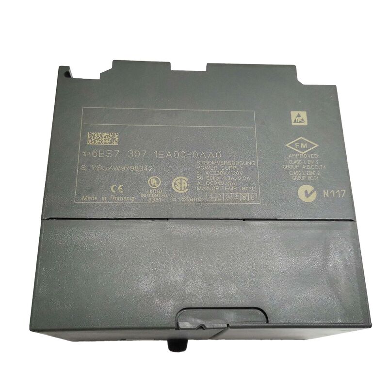
Home
>
Products
>
PLC Programmable Logic Controller
>
The Siemens 6ES7307-1EA00-0AA0 is the 5-amp version of the SIMATIC PS 307 power supply module — the dedicated AC-to-DC converter that every standard S7-300 controller system begins with. Before any CPU, signal module, or expansion module can operate, the PS 307 must convert the facility's AC mains supply into the stabilised 24V DC that runs the S7-300 backplane and provides the load voltage for field devices.
The relationship between the PS 307 and the S7-300 station is fundamental: the PS 307 is not an accessory or an option. It is the station's electrical starting point.
Where some control systems demand separate external power supplies for the PLC and for field device loads, the PS 307 is designed to serve both roles from a single unit.
The 24V DC output supplies the S7-300 system voltage (powering the CPU, the backplane bus, and all installed modules) and can simultaneously supply 24V DC to field I/O — proximity sensors, solenoid valve coils, contactor control circuits, indicator lamps — all drawing from the same regulated 24V rail.
The 5A output capacity (120W at 24V) is sized to handle a fully equipped S7-300 rack plus a reasonable I/O field load.
The automatic voltage range switching is a practical benefit that makes the PS 307 a genuinely universal power supply. No jumper to move, no selector switch to set correctly, no risk of applying 230V AC to a supply configured for 120V input.
The PS 307 internally detects the input voltage and adjusts its rectification and regulation circuit accordingly — connecting to 120VAC mains in North America, or 230VAC mains in Europe, or any nominal voltage in between that falls within the permitted range, produces the same 24V DC output.
| Parameter | Value |
|---|---|
| Input Voltage | 120/230VAC (auto) |
| Input Frequency | 47–63Hz |
| Output Voltage | 24VDC |
| Output Current | 5A |
| Power Consumption | 138W |
| Efficiency | 87% |
| Power Loss | 18W typical |
| Inrush Current | 20A at 25°C |
| I²t | 1.2 A²s |
| Isolation | 250VAC (EN 60950) |
| Dimensions (W×H×D) | 80×125×120mm |
| Weight | 740g |
The PS 307's 87% efficiency — at 138W input, 120W of usable 24V DC output, with 18W dissipated as heat — has practical implications for cabinet thermal design.
In a control cabinet, every watt of power loss becomes heat that must be managed. An 18W loss from the power supply alone contributes meaningfully to the cabinet's total heat dissipation requirement. When combined with the heat from a CPU module (typically 4–6W), several signal modules (40–80mW per module), and any function modules or communication processors in the rack, the total cabinet heat load is easily 30–50W for a mid-size S7-300 installation.
Cabinet manufacturers specify maximum allowable internal ambient temperatures (typically 40°C or 55°C depending on module ratings).
If the cabinet's natural convection cannot remove the total heat load quickly enough, the internal temperature rises, eventually exceeding module ratings and causing premature failures.
The PS 307's 18W contribution to this heat budget should be included in every cabinet thermal calculation.
The PS 307's switching-mode design (as opposed to a transformer-based linear design) is what achieves 87% efficiency in a compact 80mm-wide module.
A linear supply at the same power level would typically be 50–60% efficient and would dissipate 40–60W as heat from the same 120W output — nearly three times the thermal load.
The efficiency advantage of the switch-mode PS 307 is directly visible in the cabinet's thermal performance.
When a single S7-300 station's power requirements exceed the PS 307's 5A output, two PS 307 5A modules can be connected in parallel on the same 24V DC output bus — delivering a combined 10A.
This parallel operation requires matching the output voltage trim of both supplies so that one does not carry a disproportionately higher share of the current.
The PS 307's design supports parallel operation, and both modules share the load current without requiring any additional current-balancing hardware.
The parallel approach provides not only additional capacity but also a degree of redundancy: if one PS 307 fails, the other continues delivering 5A, which may be sufficient to keep critical parts of the station running.
However, this is not equivalent to a true hot-standby redundant supply (where output diodes or active load-sharing circuitry ensure no voltage dip during the handover) — when one PS 307 in a parallel pair fails, there will be a brief transition before the surviving module stabilises at its maximum output.
For applications where even a momentary 24V supply perturbation is unacceptable, dedicated redundant power supply modules with hot-swap and load-sharing circuitry should be specified.
Two front-panel features deserve attention in installation and maintenance practice:
The 24V DC LED confirms that the output voltage is within the specified regulation range. It illuminates green when the 24V output is present and within limits.
If the LED is off with AC power applied, the output is either below the threshold (overload, short circuit, or regulation fault) or the PS 307 has failed internally. Checking the LED is the first diagnostic step when a station fails to power up.
The ON/OFF switch (present on many PS 307 models) allows the 24V DC output to be switched on or off while AC mains power remains connected to the module.
This capability is used during module hot-swap operations — switching the 24V output off (so the 24V bus is dead) before removing or inserting a live signal module — when the system architecture requires it.
It also allows controlled restart of the 24V bus without disconnecting AC power, useful for fault reset procedures.
Q1: Can the PS 307 5A supply power to both the S7-300 system voltage and to field devices simultaneously, and is there a risk of overloading it if field devices draw more current than expected?
Yes, a single PS 307 output rail is intended to supply both the S7-300 system voltage (drawn by the CPU and all installed modules through the backplane) and 24V DC field loads (sensors, solenoids, lamps, contactor coils) connected to the field wiring of the I/O modules.
The total current draw from all these consumers must not exceed the 5A output rating continuously.
Calculating the actual current budget before the system is installed is essential: add the rated 24V current consumption of every S7-300 module from its datasheet (typically 80–200mA per module), the maximum field current from all sensor power supplies in the I/O circuits (each 2-wire sensor draws 4–20mA; multiple sensors aggregate quickly), and any actuator coils or lamps that are supplied from the same 24V rail.
If the total approaches or exceeds 5A, a second PS 307 module — either in parallel or supplying a separate field load rail — should be included in the design.
Overloading the PS 307 causes it to fold back its output voltage (short-circuit protection activates), potentially causing unexplained station behaviour that is difficult to trace without measuring the actual output current.
Q2: What is the purpose of the inrush current specification (20A at 25°C, I²t = 1.2 A²s), and how does it affect the selection of upstream circuit protection?
When the PS 307 is first energised — or re-energised after a brief power interruption — its internal filter capacitors must be charged from zero to the operating voltage. During this charging interval (typically lasting a few milliseconds), the instantaneous current drawn from the AC supply is far higher than the steady-state operating current.
The PS 307's 20A inrush at 25°C is the peak of this charging current transient.
The I²t value of 1.2 A²s characterises the energy content of the inrush event — the product of the square of the current and the time over which it flows — and this is the figure used to select upstream circuit breakers and fuses.
A circuit breaker with too tight a tripping characteristic (type B, which trips at 3–5× rated current instantaneously) may nuisance-trip when the PS 307 is switched on, even though no fault has occurred.
Siemens recommends a minimum 6A type C miniature circuit breaker (MCB) for single PS 307 protection — type C breakers tolerate instantaneous currents up to 10–15× rated current before tripping, which is more appropriate for the PS 307's inrush profile. If two PS 307 modules are operated in parallel, the combined inrush at startup should be considered when sizing the upstream MCB.
Q3: The PS 307 is listed as superseded by the 6ES7307-1EA01-0AA0. Are the two modules mechanically and electrically interchangeable in an existing S7-300 installation?
The 6ES7307-1EA01-0AA0 (successor) is a direct functional replacement for the 6ES7307-1EA00-0AA0 (this module).
The physical dimensions (80×125×120mm), mounting geometry (standard S7-300 rail, single slot), output specification (24VDC, 5A), input specification (120/230VAC, automatic switching), and connector placement are all identical — the successor module physically replaces the original without any cabinet modification, rail adjustment, or wiring change.
The primary difference between the two revisions is internal — the successor incorporates component updates and minor manufacturing improvements that improve reliability metrics, not user-visible specifications. When sourcing a replacement for a failed 6ES7307-1EA00-0AA0, the 6ES7307-1EA01-0AA0 is the preferred current replacement. If a new-old-stock 6ES7307-1EA00-0AA0 is installed in an existing station, it operates identically to the original.
Q4: Does the PS 307 provide any protection against brief AC input power interruptions, and what happens to the 24V output during a short power failure?
The PS 307 provides short-term power failure bridging — the output continues to deliver 24V DC for a defined minimum period after the AC input fails.
The bridging time is specified as a minimum of 5 milliseconds, with a minimum 1-second repetition rate before the next bridging interval is available.
This 5ms bridging is sufficient to ride through the brief supply interruptions caused by transient disturbances on the AC distribution system — voltage dips caused by large motor starts on the same distribution panel, brief interruptions from automatic transfer switching, or supply switching operations.
It is not sufficient to maintain operation through extended power failures — for those, an Uninterruptible Power Supply (UPS) on the AC input side is required. The 5ms bridging is a hardware characteristic of the PS 307's internal energy storage (filter capacitors); it is not user-adjustable.
The CPU 312's own power failure bridging is 5ms at the CPU supply pin, which is independent of the PS 307's bridging. In a correctly designed system, the PS 307's 5ms bridging ensures the 24V bus remains stable long enough for the CPU's own power monitoring circuits to execute an orderly controlled stop sequence if the power failure continues.
Q5: Can the PS 307 be used as a general-purpose 24VDC panel supply for devices other than the S7-300 PLC modules, and what are the installation considerations?
Yes. The PS 307's 24V DC output is not electrically differentiated between the S7-300 system voltage use and general panel load use — it provides a regulated, stabilised, short-circuit-proof 24V DC rail that can supply any 24V DC load within its 5A current capacity.
It is common practice to use the PS 307 as the sole 24V supply for a combined S7-300 station and its local field devices: the backplane bus draws current through the rail assembly, and field-wired loads (sensor supplies, valve coils, contactor control circuits) draw from the same output terminals through fused terminal strips.
The key installation consideration is grounding: the PS 307's 0V output (negative terminal) must be connected to the cabinet's PE (protective earth) system to ensure the 24V rail is properly referenced.
Floating (ungrounded) 24V DC rails create common-mode voltage conditions that can cause measurement errors in analog I/O modules and interference in communication circuits.
The PS 307 datasheet specifies the grounding connection point and the recommended wiring practice for both grounded and ungrounded 24V configurations.
![]()
Contact Us at Any Time