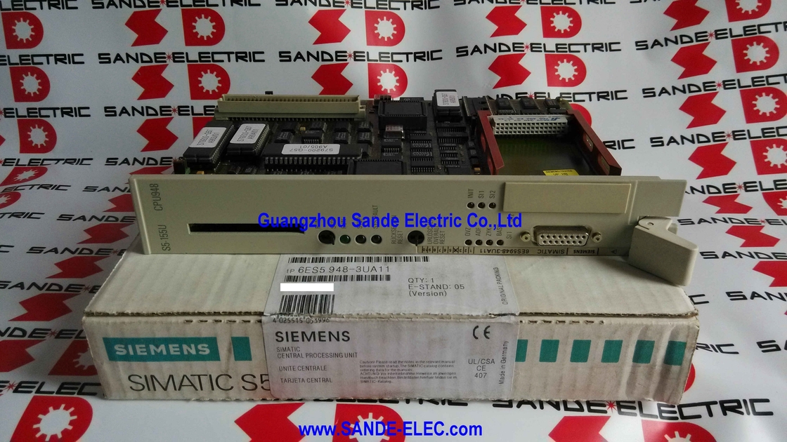
Siemens 6ES5948-3UA11 | SIMATIC S5 CPU 948 — S5-135U / S5-155U / 640KB RAM / 4MB Flash EPROM / 20mA TTY / Double-Width / Legacy Spare
The CPU Behind Siemens's Largest S5 Process Controllers
The S5-155U was not a compact machine controller — it was Siemens's full-scale process automation platform for large continuous process installations: power plant distributed control, chemical reactor management, refinery unit automation, large-scale water treatment. The applications it ran were measured in hundreds of programme blocks and hundreds of I/O points, at a scale that the smaller S5-95U and S5-115U systems were never designed to handle.
The CPU 948 is the module that processed all of it. A double-width rack module — occupying two slot positions because the electronics could not fit in one — with 640KB of working RAM, a pluggable memory submodule slot for up to 4MB of Flash EPROM programme storage, and a 20mA TTY current-loop programming interface. Today the 6ES5948-3UA11 is a maintenance spare for the S5-155U installations still in service. Process plants that justified the S5-155U in the 1990s typically justify keeping it running — migration to a modern platform is a capital project, and as long as the hardware is operational, many facilities defer it.
When a CPU 948 fails in these installations, sourcing a replacement and restoring production is the immediate priority.
Key Specifications
| Parameter |
Value |
| Part Number |
6ES5948-3UA11 |
| Internal RAM |
640 KB |
| External Memory |
Up to 4,096 KB (Flash EPROM) |
| PG Interface |
20mA TTY, 15-pin Cannon |
| PG Interface Slot |
1 pluggable |
| Memory Submodule |
1 slot |
| Module Format |
Double-width |
| Weight |
0.526 kg |
| Compatible |
S5-135U, S5-155U |
| Status |
Discontinued spare |
Memory Architecture — RAM and EPROM Submodule
The CPU 948's 640KB internal RAM holds the active, executing programme. The pluggable Flash EPROM submodule — extending memory to 4MB — serves as load memory: the non-volatile store from which the programme copies into RAM at power-up. This two-layer architecture meant that a programme larger than 640KB could still be used, loaded in sections from the EPROM into the working RAM. It also meant that power-up included a programme load phase before execution began — large S5-155U programmes took several seconds to load, which is why restart times were longer than modern controllers.
The memory submodule is the key to programme recovery after CPU replacement. If the programme is stored on the EPROM submodule, it transfers from the failed CPU to the replacement — no programming station required at power-up. Without a submodule, the programme must be downloaded via a TTY-connected STEP 5 terminal from an archived backup.
UA11 vs UA12 vs UA13 Variants
The 6ES5948-3UA11 (UA11) has 640KB RAM, one TTY programming interface socket, and one memory submodule slot. The UA12 adds a second interface socket — allowing a programming terminal and an operator panel to connect simultaneously. The UA13 reflects a later firmware revision. All variants are mechanically compatible with the S5-135U and S5-155U rack; programmes on memory submodules operate across variants subject to firmware version compatibility.
FAQ
Q1: How do you connect a modern PC to the CPU 948 for programming or diagnostics?
Via a USB-to-TTY adapter compatible with the Siemens AS511 protocol, connected to the CPU's 15-pin Cannon TTY interface. STEP 5 V7.2 or later runs on Windows XP natively or under a virtual machine on modern hardware. STEP 7 and TIA Portal do not support the S5-135U/155U generation. No direct Ethernet or USB connection is available.
Q2: How is the programme restored after fitting a replacement CPU 948?
If the programme is on the Flash EPROM memory submodule, remove it from the failed CPU and install it in the replacement. The CPU loads the programme automatically at power-up without a programming station. If no submodule is present, the programme must be downloaded from a STEP 5 archive via a TTY-connected terminal. Always back up programmes to an EPROM submodule in any production S5-155U installation.
Q3: What are the practical differences between the UA11, UA12, and UA13 variants?
UA11 (this unit): 640KB RAM, one TTY interface socket, one memory submodule slot. UA12: same RAM and memory submodule, second interface socket for simultaneous programmer and operator panel connection. UA13: later firmware revision. All are rack-mechanically and S5 backplane-electrically compatible with S5-135U/155U systems. Programmes transfer between variants via memory submodule, subject to firmware compatibility.
Q4: Can I/O modules be added to the S5-155U rack with the CPU 948 running?
Limited. The CPU 948 can recognise newly inserted modules online, but integrating them into the programme requires a STEP 5 programme modification and download. For safety-critical process applications, any hardware change should follow the site's change management procedure and be planned for a maintenance window.
Q5: What is the migration path from an S5-155U/CPU 948 installation?
The standard target is the SIMATIC S7-400, with the STEP 5-to-STEP 7 programme conversion tool assisting restructuring — though manual validation of converted code is mandatory. Phased migration using S5/S7 coupling modules allows incremental replacement while the plant continues running on the remaining S5 sections. Full migration of a large S5-155U process control system is a multi-month capital project, typically planned around a plant shutdown, with Siemens migration services available to support the engineering work.


 Your message must be between 20-3,000 characters!