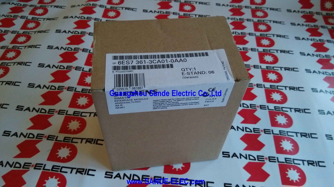
Siemens 6ES7361-3CA01-0AA0 | SIMATIC S7-300 IM 361 — Expansion Rack Receive / 24VDC / K-Bus Pass-Through / 0.8A Backplane / 10m / Phase-Out Jan 2023
What the IM 361 Provides at the Receiving End
Every expansion rack in an S7-300 IM 360/361 multi-rack configuration needs one IM 361. It receives the backplane bus extension sent by the IM 360 — or by the preceding IM 361 in a daisy chain — and distributes it to every module slot in the local expansion rack. The IM 361 does not simply pass data through; it actively powers the expansion rack's backplane bus from its 24V DC supply, providing up to 0.8A for all modules in that rack.
The K-Bus routing is the IM 361's defining advantage over the IM 365 receive module used in simpler configurations. The IM 361 routes the full K-Bus into the expansion rack, making it available to any function module installed there. FM 355 temperature controllers, FM 351 positioning modules, FM 350-2 counters, and FM 352 electronic cam controllers all require K-
Bus communication with the CPU — they can only be installed in expansion racks equipped with IM 361, never with IM 365.
In a daisy-chain configuration, the IM 361 also passes the bus onward — one cable port connects to the upstream module (IM 360 or previous IM 361), and a second cable port connects to the next IM 361 in the chain, extending the system to a second and third expansion rack.
Key Specifications
| Parameter |
Value |
| Role |
Expansion rack receive (rack 1/2/3) |
| Power |
24V DC (external) |
| K-Bus |
Yes — full pass-through |
| Backplane Current |
Max. 0.8A |
| Cable Max. |
10m to adjacent IM |
| Dimensions |
40 × 125 × 120mm |
| Weight |
~225g |
| Paired With |
IM 360 |
| Status |
Phase-out Jan 2023 |
24V DC External Power — Independent and Separately Controlled
The IM 361's 24V DC supply is not derived from the connecting cable — it is an independent field-supplied connection at the expansion rack. A PS 307 power supply module installed in the expansion rack to the left of the IM 361 is the standard solution. Alternatively, the existing panel 24V DC supply can feed the IM 361's power terminals directly if capacity allows.
This independence has a practical maintenance advantage: each expansion rack can be powered down independently for module replacement, wiring work, or maintenance, while the central rack CPU continues running if the application permits. The 0.8A backplane current the IM 361 provides is the total available for all modules in that expansion rack — a backplane current calculation is advisable for racks with high-current function modules.
Status LEDs — SF and 5VDC
SF (red): Illuminates when the connecting cable from the upstream module is missing, when the upstream module is powered off, or when the CPU is in POWER OFF state. A lit SF LED means the expansion rack has lost its bus connection.
5VDC (green): Confirms that the 5V internal logic supply on the expansion rack's backplane is present and within specification — the backplane is ready to supply modules.
FAQ
Q1: Can function modules like FM 355 or FM 351 be installed in an IM 361 expansion rack?
Yes — this is the primary technical reason to choose IM 361 over IM 365. The IM 361 routes the K-Bus into the expansion rack, giving function modules direct CPU communication access. FM 350-2, FM 351, FM 355, and FM 352 all operate normally in an IM 361 expansion rack. The same function modules cannot operate in an IM 365 expansion rack — IM 365 does not route the K-Bus.
Q2: Can IM 360/361 and IM 365 coexist in the same S7-300 station?
No. Each S7-300 CPU supports one expansion interface type — either one IM 360 (connecting up to three IM 361 units) or one IM 365 pair. The two types cannot be mixed in the same station. This decision must be made at system design time based on whether K-Bus is needed in expansion racks.
Q3: What connecting cable is required between the IM 360 and IM 361?
The connecting cable is ordered separately (e.g., 6ES7368-3BB01-0AA0 for 1m). Cables are available in standard lengths up to 10m. Standard DIN cable or generic cable cannot substitute — the connector profile is specific to the IM 360/361 interface ports. Maximum cable length between any two interface modules is 10m — a hard electrical limit.
Q4: The phase-out date is January 2023. Is the IM 361 still obtainable?
Phase-out (PM400) initiates the removal from active sales, not immediate unavailability. Products typically remain purchasable from Siemens and distributors during a transitional period as stock depletes. After Siemens inventory is exhausted, the industrial surplus market provides tested used and refurbished units. For maintenance of existing multi-rack S7-300 installations, both the IM 360 and IM 361 remain valid spare parts through the industrial supply chain.
Q5: How does the IM 361 handle the daisy-chain to additional expansion racks?
The IM 361 has two cable interface ports — one connecting upstream (to the IM 360 or preceding IM 361) and one connecting downstream (to the next IM 361 for the following expansion rack). This daisy-chain architecture allows up to three IM 361 units in the chain. Each IM 361 supplies its local rack's backplane while passing the bus and K-Bus signal forward. The maximum 10m cable limit applies independently to each cable segment in the chain.


 Your message must be between 20-3,000 characters!