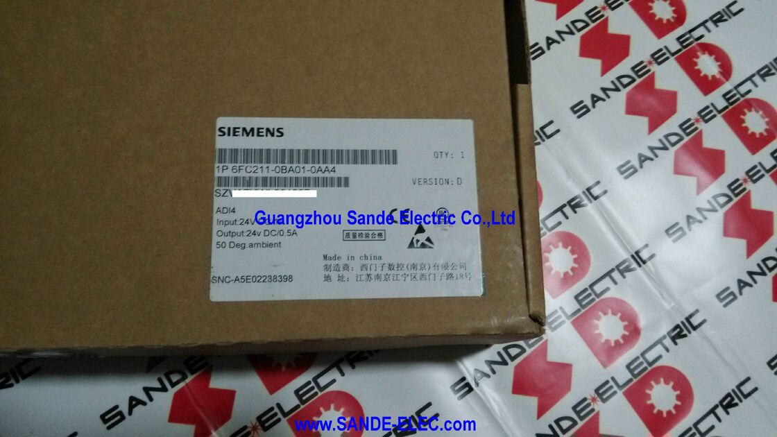
Siemens 6FC211-0BA01-0AA4 | SINUMERIK ADI4 — Analog Drive Interface for 4 Axes over PROFIBUS DP, 24V DC Input, ±10V Analog Setpoint Output, TTL/SSI Encoder, Version D
Overview
The Siemens 6FC211-0BA01-0AA4 is the ADI4 (Analog Drive Interface for 4 Axes), manufactured by Siemens' CNC-dedicated manufacturing entity in Nanjing, China. As Version D of the ADI4 hardware, this module represents a mature revision in the product's lifecycle, incorporating accumulated design refinements while maintaining full functional and software compatibility with the SINUMERIK ADI4 specification.
The ADI4's engineering role addresses a persistent integration challenge in CNC machine tool retrofits and hybrid installations: SINUMERIK CNCs communicate with servo and spindle drives over PROFIBUS DP using digital protocol messages, but a large installed base of analog servo amplifiers — including the widely deployed SIMODRIVE 611 analog series and many third-party servo amplifiers — accept speed commands only as ±10V analog voltage signals.
Without the ADI4, a system designer faces either replacing all drives (high cost, extended downtime) or foregoing the modern CNC (losing programming capability and diagnostic features). The ADI4 eliminates this choice.
Connected as a PROFIBUS DP slave on the equidistant bus, the module receives digital speed setpoints from the CNC each bus cycle, converts them to ±10V analog voltages at its four output channels, and simultaneously reads incremental or SSI encoder feedback from each axis.
The encoder data is processed internally, packaged into PROFIDrive-profile message frames, and returned to the CNC over PROFIBUS — giving the CNC controller real-time position and velocity actual values in digital form, even though the physical drives are analog.
For the CNC, the ADI4 presents four digital servo axes; for the drives, it presents four conventional ±10V analog command signals. Both sides see the interface they expect.
Key Specifications
| Parameter |
Value |
| Input Voltage |
24V DC |
| Output (encoder supply) |
24V DC / 0.5A |
| Analog Setpoint Output |
±10V DC × 4 axes |
| Encoder Input |
TTL (RS422) incremental / SSI absolute |
| PROFIBUS DP |
Equidistant DP slave, max. 12 Mbit/s |
| Axes Supported |
4 |
| PROFIBUS Address |
DIL switch S2 |
| Ambient Temperature |
Up to 50°C |
| Hardware Version |
D |
| Manufacturing |
Siemens NC (Nanjing), China |
| Related Global Variant |
6FC5211-0BA01-0AA4 |
Version D Hardware — What It Means in Practice
The "VERSION: D" marking on the product label identifies the hardware revision of this ADI4 unit. Siemens uses sequential version letters (A, B, C, D...) to track changes in the physical hardware design — component updates, PCB layout revisions, or manufacturing improvements — while the functional specification and software interface remain consistent across versions.
Version D of the ADI4 is a late-stage revision that benefits from the maturity of the design.
Early hardware versions of any embedded motion control module may carry errata related to specific operational edge cases, component tolerances, or EMC performance under particular installation conditions. Later versions address these through targeted hardware changes.
Version D units sourced from production lots of this era represent a reliable, well-characterised hardware baseline for machine installation or replacement.
From the commissioning engineer's perspective, all ADI4 hardware versions configure identically through the SINUMERIK Toolbox or SIMOTION SCOUT — the version letter does not change any parameter setting, PROFIBUS configuration step, or axis assignment procedure.
Equidistant PROFIBUS DP — The Non-Negotiable Requirement
One requirement must be clearly understood before specifying the ADI4: it operates exclusively on an equidistant (isochronous) PROFIBUS DP, not on a standard asynchronous DP segment.
Standard PROFIBUS DP runs with variable inter-cycle timing — the master polls slaves as quickly as it can, but the exact start time of each bus cycle varies slightly.
This variability is irrelevant for I/O modules but fatal for servo control: the CNC must know precisely when the speed setpoint was applied and when the encoder actual value was captured, otherwise its velocity and position controllers cannot function with the bandwidth and stiffness needed for machining.
Equidistant PROFIBUS DP enforces a fixed, repeating bus cycle time (Tdp) that is synchronised to the CNC's internal position control cycle.
Every device on the bus — including the ADI4 — transmits and receives in deterministic time slots within each Tdp period.
The ADI4 applies the received digital setpoint to its analog outputs at a fixed point in each cycle and captures the encoder counter state at the same fixed point, giving the CNC a consistent, latency-known feedback path.
The minimum Tdp supported by the ADI4 is 2ms — allowing the position control loop to run at up to 500Hz.
For most conventional milling, turning, and grinding applications, this is entirely adequate.
The equidistant PROFIBUS mode is activated and configured through the SINUMERIK startup tools or STEP 7/TIA Portal's isochronous DP configuration.
Analog Output and Encoder Input — Connection Details
Analog output (connector X3): Four ±10V DC analog output channels connect to the speed reference input (Nset or ±10V terminal) of each axis drive. Cables must be shielded twisted-pair, with the shield grounded at the drive cabinet's PE rail.
Routing analog signal cables away from power cables is essential to prevent induced noise on the low-level voltage signal — even 10–20mV of noise on a ±10V setpoint represents 0.1–0.2% velocity error at full speed, which compounds in the position loop over time.
Encoder input (connectors X4-1, X4-2, X5-1, X5-2): Each of the four encoder input connectors accepts either a TTL (5V differential, RS422) incremental encoder or an SSI absolute encoder.
The module's 24V DC output supply (24V / 0.5A) powers the encoders through the same connector — eliminating the need for a separate 24V encoder supply on axes using 24V HTL encoders with appropriate signal level adaptation, though 5V RS422 encoders draw from the module's internal 5V supply.
The encoder signals are processed through the ADI4's internal counter and interpolation circuit: each incremental encoder's A/B quadrature pulses are counted with ×4 edge detection, then multiplied by a factor of 2048 as additional fine-resolution substitute bits before transmission to the CNC via PROFIBUS.
This gives a 2500 pulse/revolution encoder an effective resolution of over 20 million counts per revolution as seen by the CNC position controller — far exceeding the mechanical accuracy of the drive system and ensuring the position loop is never limited by encoder quantisation.
Installation Environment and Derating Considerations
The label specifies 50°C as the maximum ambient temperature. This is the temperature of the air immediately surrounding the ADI4 inside the control cabinet, not the cabinet exterior temperature. In densely packed panels — particularly those also housing servo amplifiers and power supplies generating significant heat — the internal cabinet temperature may substantially exceed the external ambient.
Cabinet thermal management (ventilation, heat exchangers, fan cooling) must ensure the ADI4's location within the panel does not exceed 50°C.
The ADI4 is rated for operation inside an enclosed control cabinet only — open installation is not permissible.
The enclosure provides the required protection against conductive dust and metallic particles that are inevitably present in machine tool environments.
The protective ground screw (M6) on the ADI4 housing must be connected to the cabinet's PE rail to ensure the module's chassis ground is properly referenced and EMC performance is maintained.
FAQ
Q1: Is the 6FC211-0BA01-0AA4 the same product as 6FC5211-0BA01-0AA4 and can they be used interchangeably?
Both carry the ADI4 product name and perform the same function — analog drive interface for 4 axes over PROFIBUS DP. The 6FC211 prefix identifies the Siemens Nanjing (China) production line, while 6FC5211 is the global/European market part number.
Both variants are manufactured to the same SINUMERIK ADI4 functional specification and configure identically in the CNC's startup tools. In most machine tool applications they are interchangeable.
However, when ordering as a replacement part for a specific machine, the part number on the delivery paperwork or machine documentation should be matched, and any CNC-side hardware configuration should be verified to confirm the replacement unit's PROFIBUS GSD file version is accepted by the existing NCU software.
Q2: The output is listed as "24V DC / 0.5A." Is this a separate power supply output, or is it the encoder supply?
The 24V DC / 0.5A output on the ADI4 is the encoder power supply — a regulated, short-circuit-protected 24V output that powers HTL encoders (which require 24V supply) connected to the ADI4's encoder input channels.
The 0.5A limit is the total combined current available for all four encoder channels; each encoder typically draws 50–200mA. Encoders exceeding the total 0.5A budget require an external 24V supply.
TTL (5V) encoders draw from the ADI4's own internal 5V supply and do not consume the 24V / 0.5A output.
Q3: How is the PROFIBUS address set on the ADI4, and when does a new address take effect?
The PROFIBUS address is set using the DIL switch block S2 on the ADI4 module. The switches encode the address in binary format; the acceptable address range is 1 to 125 (PROFIBUS standard addressing, excluding reserved addresses).
A newly set address takes effect only after a power OFF/ON cycle — changing the switch position while the module is powered does not change the active address immediately. The address set on S2 must exactly match the slave address assigned to this ADI4 in the CNC's hardware configuration (Toolbox or HW Config); a mismatch causes the ADI4 to fail to join the PROFIBUS DP ring at startup.
Q4: Can two ADI4 modules be configured on the same PROFIBUS DP ring, and what is the maximum total number of axes?
Multiple ADI4 modules can operate on the same equidistant PROFIBUS DP ring, each with its own PROFIBUS address and four analog axis channels.
Up to four ADI4 modules can typically be configured per CNC system depending on the CNC type (802D, 840D, 840Di), giving a maximum of 16 analog drive axes total in a fully ADI4-based system.
Each module must be at a unique PROFIBUS address, and the combined PROFIBUS communication load of all ADI4 slaves plus any other DP slaves must remain within the minimum equidistant cycle time (Tdp ≥ 2ms) that all ADI4 modules can satisfy.
Q5: What diagnostic information do the ADI4's LED indicators provide during troubleshooting?
The ADI4 has two dual-function LEDs, H1 and H2, each displaying two states depending on the fault condition:
H1 (PW/TMP): When lit solid, it indicates normal power-on status.
When H1 indicates a TMP (temperature) fault, it signals that the module's internal temperature has exceeded the protection threshold — an overtemperature condition that may result from inadequate cabinet ventilation or excessive ambient temperature at the module's location.
H2 (EXCH/RDY): In normal operation, H2 lit solid indicates that the module is ready and in active PROFIBUS communication (RDY). H2 flashing indicates that a PROFIBUS message frame exchange (EXCH) is actively occurring — during startup negotiation or parameter download.
H2 off while H1 is lit typically indicates that the PROFIBUS connection is established at the physical layer but no cyclic data exchange is taking place — check PROFIBUS address match and CNC hardware configuration.


 Your message must be between 20-3,000 characters!